
Improved grinding device

An improved, electric connection technology, applied in the direction of coupling devices, parts of connecting devices, devices to prevent contact with live contacts, etc. The effect of security risks

Inactive Publication Date: 2018-05-04
贾军霞
View PDF6 Cites 2 Cited by
  • Summary
  • Abstract
  • Description
  • Claims
  • Application Information

AI Technical Summary

Problems solved by technology

[0002] In some workpiece processing factories, hand-held grinders are often used to grind and polish the surface of the workpiece. The hand-held grinder can only perform grinding work after the power supply is plugged in. Traditionally, the sockets of the grinder are generally connected to the mains. The internal conductive sheet is set relatively outside, which may cause electric shock accidents if accidentally touched by humans, and there is a large safety hazard. The friction is used to achieve the locked state, but this locking method is extremely unstable. After plugging, it is very easy to be affected by dragging and pulling the power supply line, resulting in loose plugging, which interrupts the power supply and brings great inconvenience to the grinding work.

Method used


Image

  • Improved grinding device
  • Improved grinding device
  • Improved grinding device

Examples


Embodiment Construction

[0030] Combine below Figure 1-11 The present invention will be described in detail.

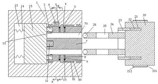
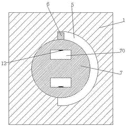
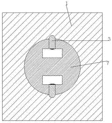
[0031] refer to Figure 1-11 , an improved grinding device according to an embodiment of the present invention, including an electrical coupling seat 1 and an electrical coupling head 20 connected to the grinding machine, and the electrical coupling head 20 is provided with a first annular groove 21 whose opening is towards the left end , a pipe sleeve 23 is movably installed in the first annular groove 21, and an electric connecting rod 24 located in the pipe sleeve 23 is correspondingly installed on the left end surface of the electric coupling head 20, and the electric connecting rod 24 There is a through groove 25 that penetrates up and down in the middle; the electrical joint head 20 is also provided with a hand grasping part, the hand grasping part includes a convex strip 211 and a rubber pad 212, and the electrical joint seat 1 is provided with a central groove , a twisting member 7...


PUM


Abstract

The invention discloses an improved grinding device, which comprises an electric connection socket and an electric connection plug connected with a grinding machine, wherein first ring surface groovesof which open ends are toward the left end are formed in the electric connection plug; a sleeve is movably arranged in each first ring surface groove; electric connection rods located in the sleevesare correspondingly arranged on the left end surface of the electric connection plug from top to bottom; a penetrating groove which penetrates up and down is arranged in each electric connection rod;a central groove is arranged in the electric connection socket; a twisting part is movably arranged in the central groove; insert cavities matched with the electric connection rods are correspondinglyarranged in the twisting part from top to bottom; a first power transmission pin is fixedly arranged at the left side of an inner wall of each insert cavity; upper and lower corresponding first pin openings of which the open ends are toward the left, and front and back corresponding second pin openings are also formed in the left end surface of the twisting part; a groove body of which the open end is toward the left is arranged in the center of the left end surface of the twisting part; second power transmission pins are fixedly arranged on upper and lower end walls of the groove body; a sliding push groove is formed in the left end of the central groove in the electric connection socket; and a sliding push block is arranged in the sliding push groove in a manner of moving from left to right.

Description

technical field [0001] The invention relates to the field of grinding machine power supply, in particular to an improved grinding device. Background technique [0002] In some workpiece processing factories, hand-held grinders are often used to grind and polish the surface of the workpiece. The hand-held grinder can only perform grinding work after the power supply is plugged in. Traditionally, the sockets of the grinder are generally connected to the mains. The internal conductive sheet is set relatively outside, which may cause electric shock accidents if accidentally touched by humans, and there is a large safety hazard. The friction is used to achieve the locked state, but this locking method is extremely unstable. After plugging, it is very easy to be affected by dragging and pulling the power supply line, resulting in loose plugging, which interrupts the power supply and brings great inconvenience to the grinding work. . Contents of the invention [0003] The objec...

Claims


Application Information

Patent Timeline
Patent Type & Authority Applications(China)
IPC IPC(8): H01R13/639H01R13/629H01R13/44B24B23/00
CPCH01R13/639B24B23/00H01R13/44H01R13/629
Inventor 贾军霞何杨波
Owner 贾军霞
Learn More