
Turntable laser pcb separating machine and method

A pcb board and board splitter technology, applied in laser welding equipment, electrical components, printed circuit manufacturing, etc., can solve the problems of low board splitting efficiency, pcb board deformation, uneven strength, etc., to achieve automation and simplification of structure , the effect of structural stability

Pending Publication Date: 2018-05-08
SHENZHEN BEYOND LASER TECH CO LTD
View PDF1 Cites 2 Cited by
  • Summary
  • Abstract
  • Description
  • Claims
  • Application Information

AI Technical Summary

Problems solved by technology

[0002] Pcb boards are used more and more widely, and are one of the necessary remote parts in the field of electric control. The demand for pcb boards is increasing, and the problem of pcb board division also exists. The existing industrial pcb board division boards Most of the methods use manual splitting, which causes uneven strength and deformation of the pcb board. There are many burrs on the edge of the splitting board, and the splitting efficiency is low, which requires a lot of labor. , but did not solve the problem comprehensively, such as the lack of burrs in the knife-type splitter, and the stress in the stamping splitter. Patent No. CN201611126153.6 discloses a fully closed-loop PCB laser automatic splitter and splitter Although the plate method solves the above problems, its conveying structure is complicated and the cost is high

Method used


Image

  • Turntable laser pcb separating machine and method
  • Turntable laser pcb separating machine and method
  • Turntable laser pcb separating machine and method

Examples


Embodiment Construction

[0046] The following will clearly and completely describe the technical solutions in the embodiments of the present invention with reference to the accompanying drawings in the embodiments of the present invention. Obviously, the described embodiments are only some of the embodiments of the present invention, not all of them. Based on the embodiments of the present invention, all other embodiments obtained by persons of ordinary skill in the art without making creative efforts belong to the protection scope of the present invention.

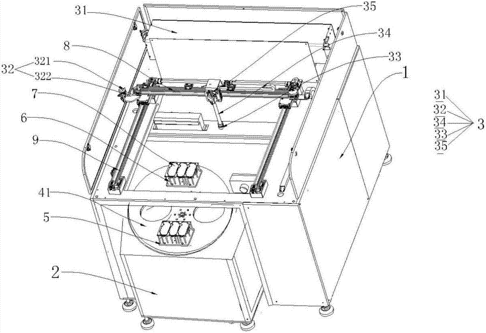
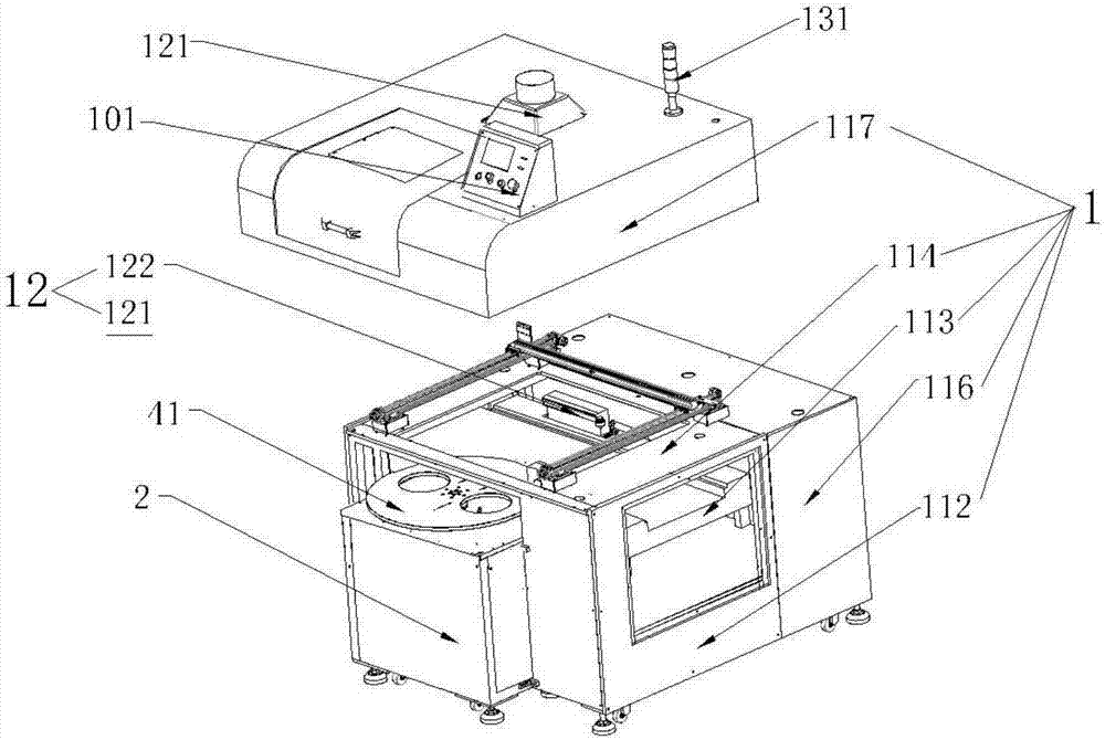
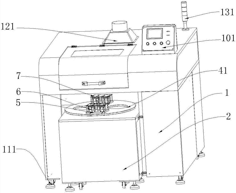
[0047] see Figure 1-Figure 3 , a turntable laser pcb board splitting machine provided by the present invention is provided with a cabinet, the cabinet body includes a board splitting cabinet 1 and a feeding cabinet 2, and the board splitting cabinet 1 is provided with an electric control component 10, a cooling component 14 and a laser component 3, the conveying cabinet 2 is provided with a conveying component 4, the electric control component 1...


PUM


Abstract

The invention provides a turntable laser pcb separating machine and method. The turntable laser pcb separating machine is provided with a cabinet body. The cabinet body comprises a pcb separating machine cabinet and a material conveying cabinet. An electric control assembly, a cooling assembly and a laser assembly are arranged inside the pcb separating machine cabinet. The material conveying cabinet is provided with a conveying assembly. The electric control assembly controls the cooling assembly, the laser assembly and the conveying assembly. The conveying assembly comprises a turntable arranged above the material conveying cabinet and an induction motor arranged inside the material conveying cabinet. The turntable and the induction motor are connected through a rotating pillar. The induction motor drives the turntable so as to drive a jig to rotate to the position below the laser assembly, and the laser assembly is used for cutting pcbs. The jig is provided with positioning pillars used for placing the pcbs. The induction motor drives the turntable so as to drive the jig to rotate by 180 degrees after cutting is completed, and the cut pcbs are output. According to the turntable laser pcb separating machine and method, the turntable is used for conveying the pcbs, the structure is simple and stable, and contactless pcb separating in laser separating is realized. Moreover, theautomatic pcb separating process is achieved, the labor intensity is relieved and production efficiency is improved.

Description

technical field [0001] The invention relates to the field of PCB splitters, in particular to a turntable laser PCB splitter and a method thereof. Background technique [0002] Pcb boards are used more and more widely, and are one of the necessary remote parts in the field of electric control. The demand for pcb boards is increasing, and the problem of pcb board division also exists. The existing industrial pcb board division boards Most of the methods use manual splitting, which causes uneven strength and deformation of the pcb board. There are many burrs on the edge of the splitting board, and the splitting efficiency is low, which requires a lot of labor. , but did not solve the problem comprehensively, such as the lack of burrs in the knife-type splitter, and the stress in the stamping splitter. Patent No. CN201611126153.6 discloses a fully closed-loop PCB laser automatic splitter and splitter Although the board method solves the above problems, its conveying structure i...

Claims


Application Information

Patent Timeline
Patent Type & Authority Applications(China)
IPC IPC(8): B23K26/38B23K26/70H05K3/00
CPCH05K3/0052B23K26/38B23K26/70B23K26/702
Inventor 陈应滨
Owner SHENZHEN BEYOND LASER TECH CO LTD
Learn More