
Full closed-loop automatic laser board splitting machine and method for PCBs

A technology of PCB board and board splitter, which is applied in laser welding equipment, printed circuit, manufacturing tools, etc., can solve the problems of unguaranteed yield, increased processing cost, high labor intensity, etc., and achieves high production efficiency and improved processing accuracy. , the effect of low labor intensity

Active Publication Date: 2017-02-22
WUHAN LINGYUN PHOTOELECTRONICS SYST
View PDF11 Cites 15 Cited by
  • Summary
  • Abstract
  • Description
  • Claims
  • Application Information

AI Technical Summary

Problems solved by technology

[0004] 1. The processing dust will pollute the PCB board, so the separated small PCB boards need to be cleaned twice, and the increased process also increases the processing cost;
[0005] 2. The vibration generated in the milling process may damage the internal copper foil of the multi-layer PCB board, which will cause the yield rate to not be guaranteed at 100%;
[0006] 3. A specific fixture is required to target a specific PCB board, so the cost of the fixture is too high
However, the initial laser splitting is actually a marking machine mode splitting, and it belongs to a single-piece production operation, with relatively low efficiency and high labor intensity.

Method used


Image

  • Full closed-loop automatic laser board splitting machine and method for PCBs
  • Full closed-loop automatic laser board splitting machine and method for PCBs
  • Full closed-loop automatic laser board splitting machine and method for PCBs

Examples


Embodiment Construction

[0038] The technical solutions in the present invention will be clearly and completely described below in conjunction with the accompanying drawings in the present invention.

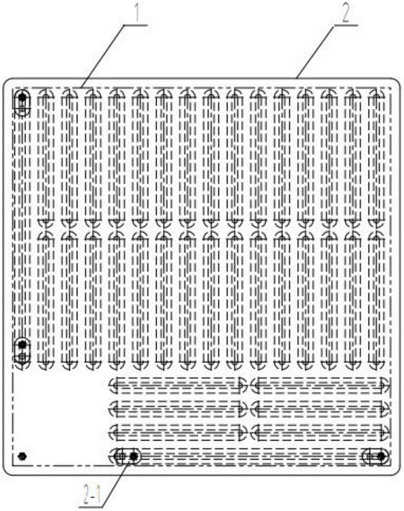
[0039] Please refer to Figure 2-9 , The fully closed-loop PCB board laser automatic splitter of the present invention includes a laser splitter 3, a jig 2, a laser cutting mechanism, a circular automatic feeding mechanism, a snatch mechanism 12, a control system 20, and an image recognition system (CCD system) 21.

[0040]The laser cutting mechanism is located on the upper part of the laser splitter 3, including a laser 4, an upper 45° full-reflection lens 5, a warning light 6, a lower 45° full-reflection lens 7, a flight node 45° full-reflection lens 8, and a two-dimensional scanning vibrator. Lens 9, X-direction workbench 10, Y-direction workbench 11, the circular automatic feeding mechanism is located below the laser cutting mechanism, including a left conveyor belt 13, an upper conveyor belt 14, a ...


PUM


Abstract

The invention provides a full closed-loop automatic laser board splitting machine for PCBs. The full closed-loop automatic laser board splitting machine comprises a laser board splitting machine body, a laser cutting mechanism, a circulating automatic feeding mechanism, a grabbing and lifting mechanism, a control system and an image recognition system. The circulating automatic feeding mechanism is arranged on the laser board splitting machine body. The laser cutting mechanism, the grabbing and lifting mechanism and the image recognition system are located above the circulating automatic feeding mechanism. The circulating automatic feeding mechanism is used for conveying a jig to the position of the grabbing and lifting mechanism, and the jig is used for loading the PCBs. The grabbing and lifting mechanism is used for elevating the jig to the position of the focus of the laser cutting mechanism. The image recognition system is used for shooting the PCBs and sending a shooting result to the control system. The control system controls the laser cutting mechanism to cut PCB areas on the multiple integrated PCBs according to the shooting result, and the grabbing and lifting mechanism is also used for arranging the jig on the circulating automatic feeding mechanism for recycling. By means of the full closed-loop automatic laser board splitting machine, full-automatic laser board splitting is achieved, the labor intensity can be effectively reduced, and the production efficiency is improved.

Description

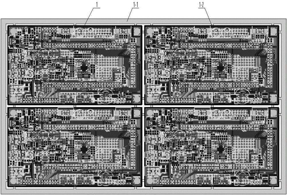
technical field [0001] The invention relates to the technical field of PCB board processing, in particular to a full-closed-loop PCB board laser automatic board splitting machine and a board splitting method. Background technique [0002] Generally, the PCB boards used in electrical appliances are relatively small, which is caused by the need for miniaturization and miniaturization of electrical appliances. A large PCB board, and finally these large integrated PCB boards are divided into small unit PCB boards, which is the sub-board of the PCB board, for example figure 1 The PCB board can be split into four small PCB boards. The process of dividing the board is to cut off the connection point 1-2, and at the same time separate the side board 1-1, and finally get four small PCB boards. [0003] Conventional PCB board splitting methods use machine milling to split boards. This method is transplanted from mechanical processing, but there are many problems: [0004] 1. The pr...

Claims


Application Information

Patent Timeline
Patent Type & Authority Applications(China)
IPC IPC(8): B23K26/38B23K26/402B23K26/70B23K101/42
CPCB23K26/38B23K26/402B23K26/702B23K2101/42
Inventor 任振红
Owner WUHAN LINGYUN PHOTOELECTRONICS SYST
Learn More