
Shearing and bending equipment for thin metal plates

A metal plate and equipment technology, applied in the field of shearing and bending equipment, can solve the problems of shearing knife wear, inconvenient operation, poor shearing effect of metal plates, etc., achieve balanced shearing force, facilitate production operations, and improve cutting effect of effect

Active Publication Date: 2019-12-20
江苏磊澄智能机械装备有限公司
View PDF5 Cites 0 Cited by
  • Summary
  • Abstract
  • Description
  • Claims
  • Application Information

AI Technical Summary

Problems solved by technology

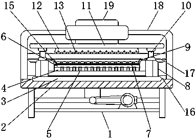
[0003] The object of the present invention is to provide a kind of shearing and bending equipment for thin metal plates to solve the problem that the metal plates proposed in the above background technology are usually bent after shearing, and workers need to straighten and bend the metal plates during the transmission process. Auxiliary operations such as adjustments are time-consuming, the shearing effect of the metal sheet is poor, the shearing knife is severely worn, and the operating platform is difficult to control the angle deflection, which is inconvenient for actual operation.

Method used


Image

  • Shearing and bending equipment for thin metal plates
  • Shearing and bending equipment for thin metal plates
  • Shearing and bending equipment for thin metal plates

Examples


Embodiment Construction

[0017] The following will clearly and completely describe the technical solutions in the embodiments of the present invention with reference to the accompanying drawings in the embodiments of the present invention. Obviously, the described embodiments are only some, not all, embodiments of the present invention. Based on the embodiments of the present invention, all other embodiments obtained by persons of ordinary skill in the art without making creative efforts belong to the protection scope of the present invention.

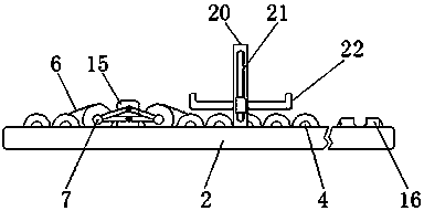
[0018] see Figure 1-4 , the present invention provides a technical solution: a thin metal sheet shearing and bending equipment, including a bracket 1, an upper cutter head 12 and a vertical rod 20, a horizontal platform 2 is fixed above the bracket 1, and a horizontal platform 2 is fixed above the horizontal platform 2 An operation platform 3 is provided, and the surfaces of the horizontal platform 2 and the operation platform 3 are attached to each other, an...


PUM


Abstract

The invention discloses shearing and bending equipment of a thin metal plate. The shearing and bending equipment comprises a support, an upper cutter disc and a vertical rod, wherein a horizontal table is fixed above the support, and an operation table is arranged above the horizontal table; conveying rollers are installed above the operation table, and sand rings are welded on the surface of theconveying rollers; supporting plates are arranged above the sand rings, and rolling shafts are arranged above the supporting plates; baffles are fixedly arranged on the left side and the right side ofthe conveying rollers, and clamping plates are arranged above the baffles; a lifting rod is arranged on the outer side of the clamping plates, and a cross rod is arranged above the lifting rods; a cutting knife is arranged below the upper cutter disc, and the upper cutter disc is located in the middle of the cross rod; a grinding disc is arranged on the surface of the cutting knife, and a lower cutter disc is arranged below the cutting knife; a sliding groove is fixed in the middle of the vertical rod, and the vertical rod is located on the left side of a bending bottom plate. The shearing bending equipment of the thin metal plate can achieve continuous machining of shearing and bending, shear force is balanced, and the operation table can freely deflect the angle.

Description

technical field [0001] The invention relates to the technical field of metal processing devices, in particular to a shearing and bending equipment for thin metal plates. Background technique [0002] The shearing machine uses the moving upper blade and the fixed lower blade to apply shear force to metal sheets of various thicknesses with a reasonable blade gap, so that the sheets are broken and separated according to the required size. Bending is a kind of processing Form, by bending the metal plate to make the metal plate achieve the desired bending effect. However, the existing metal sheets are generally bent after being cut. During the transmission process, workers need to perform auxiliary operations such as straightening and adjusting the metal sheet, which consumes man-hours. The cutting effect of the metal sheet is poor, and the wear of the shearing knife Seriously, it is difficult to control the angle deflection of the operating platform, which is inconvenient for a...

Claims


Application Information

Patent Timeline
Patent Type & Authority Patents(China)
IPC IPC(8): B23P23/04B23D15/06B23D33/02
CPCB23D15/06B23D33/02B23P23/04
Inventor 钮万和
Owner 江苏磊澄智能机械装备有限公司
Learn More