Cement paste mixer for laboratory

A technology for cement slurry and laboratory use. It is used in cement mixing devices, clay preparation devices, and mixing operation control devices. It can solve the problems of constant cleaning, short switching time, and mechanical damage to cleaning personnel, saving time. , to avoid the tedious process, to eliminate the effect of mechanical damage

Pending Publication Date: 2018-05-08
NANJING INST OF TECH
View PDF0 Cites 4 Cited by
  • Summary
  • Abstract
  • Description
  • Claims
  • Application Information

AI Technical Summary

Problems solved by technology

Mixing is divided into low-speed mixing and high-speed mixing. In the process of switching from low-speed mixing to high-speed mixing, it is necessary to manually clean the cement mortar remaining on the mixing blades. The existing problem is that the time for switching between the two mixin

Method used


Image

  • Cement paste mixer for laboratory
  • Cement paste mixer for laboratory
  • Cement paste mixer for laboratory

Examples


Embodiment Construction

[0022] The specific implementation manners of the present invention will be further described below in conjunction with the accompanying drawings, and this embodiment does not constitute a limitation to the present invention.

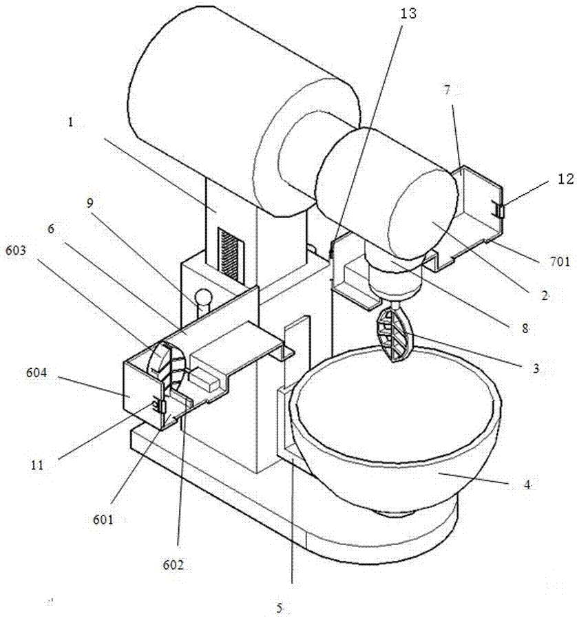
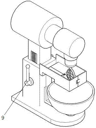
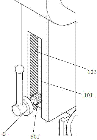
[0023] Such as figure 1 As shown, a cement slurry mixer for laboratory use includes a body 1, a motor transmission device 2, a stirring blade 3, a stirring pot 4, a fixed pallet 5, a first scraper device 6, a second scraper device 7, a trigger Single-chip microcomputer 8, first driving handle 9, second driving handle 10, circlip structure button 11, circlip block 12, torsion spring 13.

[0024] The upper part of the body 1 is provided with a motor transmission device 2, and the lower part of the motor transmission device 2 is provided with a stirring blade 3. The motor transmission device 2 is connected to the stirring blade 3. The stirring blade 3 is leaf-shaped, and the frame and the leaf stem of the stirring blade 3 are solid parts. , there is a gap...


PUM


Abstract

The invention discloses a cement paste mixer for a laboratory. A mixer body is provided with a motor transmission device. A mixing blade is arranged below the motor transmission device. The motor transmission device is connected with the mixing blade and a triggering single-chip microcomputer. The mixing blade is in a leaf shape. A mixing pan is arranged under the mixing blade and detachably arranged on a fixing supporting plate. The two sides of the mixer body are rotationally provided with a first scraper blade device and a second scraper blade device. The first scraper blade device and thesecond scraper blade device are symmetrically arranged about the center axis of the mixer body. The first scraper blade device is provided with a die in a sliding manner, and the die is in an invertedleaf shape. The die and the mixing blade are provided with the same frame structure. When the mixing blade and the die are located on the same horizontal line, gaps of the mixing blade correspond tothe solid part of the die, the solid part of the mixing blade corresponds to gaps of the die, and the die is electrically connected with the triggering single-chip microcomputer. According to the cement paste mixer for the laboratory, efficiency is improved, time is saved, and the cement paste on the mixing blade is effectively cleared away.

Description

technical field [0001] The invention relates to the field of mixers, in particular to a laboratory cement paste mixer. Background technique [0002] In the prior art, when the cement slurry mixer is used, cement and water are placed in the mixing pot, and then the stirring pot is placed on the fixed supporting plate, and then the driving handle is turned to lift the fixed supporting plate, so that the stirring pot is raised to the level of stirring. position, and then turn on the machine for stirring. Mixing is divided into low-speed mixing and high-speed mixing. In the process of switching from low-speed mixing to high-speed mixing, it is necessary to manually clean the cement mortar remaining on the mixing blades. The existing problem is that the time for switching between the two mixing processes is too short, and manual cleaning is required. There are not only the problems of invariable cleaning and incomplete cleaning, but also the problem that the mixer has started to...

Claims


Application Information

Patent Timeline
IPC IPC(8): B28C5/16B28C7/00
CPCB28C5/16B28C7/00
Inventor 蒋沅峰陆李和顾云凡
Owner NANJING INST OF TECH
Why Eureka
Try Eureka