Headstall with tension detecting function

A bridle and tension technology, which is applied in the direction of tension measurement, measurement, and parts of connecting devices, can solve the problems that tension detection equipment is not suitable for the internal environment of oil wells, and the value of tension sensors is expensive, so as to prevent damage to tension sensors and realize integration The effect of installation

Pending Publication Date: 2018-05-08
HEILONGJIANG LANDE ULTRASONIC TECH CO LTD
View PDF0 Cites 10 Cited by
  • Summary
  • Abstract
  • Description
  • Claims
  • Application Information

AI Technical Summary

Problems solved by technology

However, during oil drilling, the cable goes deep into the oil well, and the traditional tension detection equipment is not suitable for the internal environment of the oil well; and when measuring the force inside the oil well, it is necessary to comprehensively consider the influence of the pressure difference between the inside and outside of the instrument on the structural strength of the equipment and the detection value
At the same time, due to the high value of the tension sensor, how to protect the tension sensor when the tension is too large is also one of the technical problems faced by the tension detection of oil well cables today.

Method used


Image

  • Headstall with tension detecting function
  • Headstall with tension detecting function
  • Headstall with tension detecting function

Examples


specific Embodiment approach 1

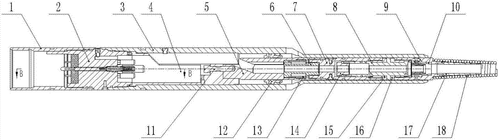
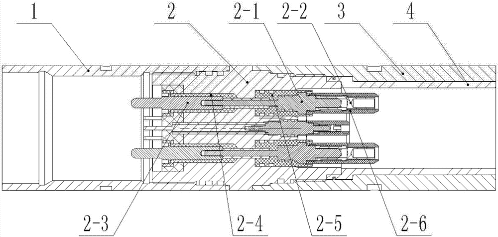
[0024] Combine below Figure 1-4 Describe this embodiment, a bridle with tension detection, including interface sleeve 1, pin joint 2, salvage cap shell 3, anti-rotation body 4, piston tube 5, tension sensor 6, tension connection sleeve 7, sealing body 8. Cone frame 9 and three-cone sleeve 10, the interface sleeve 1 is fixedly connected to the left end of the pin joint 2, the salvage cap shell 3 is fixedly connected to the right end of the pin joint 2, and the anti-rotation body 4 Snapped inside the fishing cap shell 3, the anti-rotation body 4 is located at the right end of the pin joint 2, the right end of the anti-rotation body 4 is fixedly connected to the piston tube 5, and the right end of the piston tube 5 is fixedly connected to the tension sensor 6 , the right end of the tension sensor 6 is fixedly connected to the tension connection sleeve 7, the right end of the tension connection sleeve 7 is connected to the sealing body 8, the right end of the sealing body 8 is co...

specific Embodiment approach 2

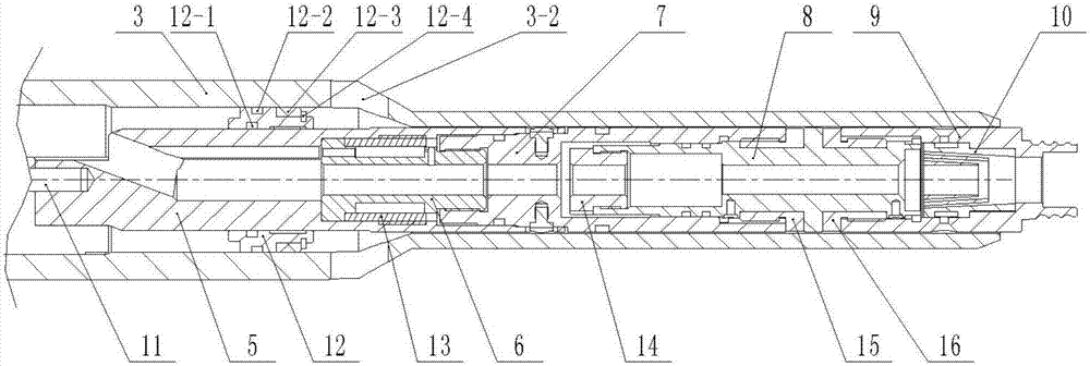
[0027] Combine below Figure 1-4 This embodiment will be described, and this embodiment will further describe Embodiment 1. A safety tension pin 11 is arranged between the anti-rotation body 4 and the piston tube 5, and one end of the safety tension pin 11 is connected to the anti-rotation body 4 by threads. The other end of the safety tension pin 11 is threadedly connected to the piston tube 5; the tensile force on the safety tension pin 11 is the same as that on the tension sensor 6, and when the tension on the safety tension pin 11 is too large, it is close to the limit of the cable tension Or when exceeding the detection range of the tension sensor 6, the safety tension pin 11 is broken due to being subjected to the ultimate tension force, so that the piston tube 5, the tension sensor 6, the tension connection sleeve 7, the sealing body 8, the cone frame 9 and the three-taper sleeve 10 are separated from the The salvage cap shell 3 slides out, and the piston tube 5, the te...

specific Embodiment approach 3

[0028] Combine below Figure 1-4Describe this embodiment, this embodiment will further explain Embodiment 1, the piston tube 5 is sleeved and connected to the balance piston 12, the balance piston 12 is slidably connected to the piston tube 5, and the balance piston 12 is provided with an inner seal Ring groove 12-1, outer sealing ring groove 12-2, sealing washer 12-3 and washer snap ring 12-4, the inner sealing ring groove 12-1 is provided with an inner sealing ring, and the outer sealing ring groove 12 -2 is provided with an outer sealing ring, the inner sealing ring is located between the balance piston 12 and the piston tube 5, the outer sealing ring is located between the balance piston 12 and the inner wall of the fishing cap shell 3, and the sealing gasket 12- 3 is socketed on the balance piston 12, the washer snap ring 12-4 is snapped on the balance piston 12, the sealing washer 12-3 is snapped between the balance piston 12 and the washer snap ring 12-4, the The seali...


PUM


Abstract

The invention relates to the technical field of oil cable connecting, in particular to a headstall with a tension detecting function. The headstall comprises a connecting port connecting sleeve, an inserting pin connector, a fishing cap shell, an anti-rotation body, a piston pipe, a tension sensor, a tension connecting sleeve, a sealing body, a conical body frame and a three-conical sleeve. The connecting port connecting sleeve is fixedly connected to the left end of the inserting pin connector, the fishing cap shell is fixedly connected to the right end of the inserting pin connector, and pressing bolts for pressing the three-conical sleeve are connected to the conical body frame in a threaded fit mode. The inserting pin connector, the anti-rotation body, the piston pipe, the tension connecting sleeve, the sealing body and the conical body frame are sequentially inserted into the fishing cap shell from left to right. The headstall with the tension detecting function has the beneficialeffects that the headstall can go deep into an oil well for cable and circuit connection, and the functions of balancing inner and outer pressure and accurately measuring cable tension are achieved;and when the tension is too large, the tension sensor can be disconnected and protected, and the advantages that assembling is convenient and the integrated extent is high are achieved.

Description

technical field [0001] The invention relates to the technical field of petroleum cable connection, in particular to a bridle with tension detection. Background technique [0002] Usually, a cable tension meter is used for line tension detection to ensure that the tension meets the cable strength requirements. However, during oil drilling, the cable goes deep into the oil well, and the traditional tension detection equipment is not suitable for the internal environment of the oil well; and when measuring the force inside the oil well, it is necessary to comprehensively consider the influence of the pressure difference inside and outside the instrument on the structural strength of the equipment and the detection value. At the same time, because the tension sensor is expensive, how to protect the tension sensor when the tension is too large is also one of the technical problems faced by the tension detection of oil well cables today. Contents of the invention [0003] The p...

Claims


Application Information

Patent Timeline
Patent Type & Authority Applications(China)
IPC IPC(8): E21B47/00E21B47/007E21B47/01E21B47/017E21B17/02H01R13/40H01R13/02H01R13/502G01L5/04
CPCE21B17/023E21B47/00E21B47/007E21B47/01E21B47/017G01L5/04H01R13/02H01R13/40H01R13/502
Inventor 张修全高曼琦迟毅徐喜任耀军
Owner HEILONGJIANG LANDE ULTRASONIC TECH CO LTD
Why Eureka
Try Eureka