Oil mist separator
An oil mist separator, oil separation technology, applied in the direction of machine/engine, engine components, mechanical equipment, etc., can solve the problems of poor setting, large space, etc., to reduce the installation space, increase the collection rate, and avoid interference. Effect
- Summary
- Abstract
- Description
- Claims
- Application Information
AI Technical Summary
Problems solved by technology
Method used
Image
Examples
no. 1 approach
[0032] First, an oil mist separator according to a first embodiment of the present invention will be described with reference to the drawings.
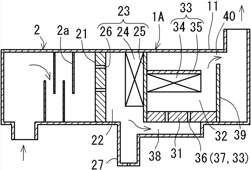
[0033] The oil contained in the blow-by gas generated in the engine is separated in the process of passing through the oil mist separator, and then returns to the intake system and is re-combusted. On the other hand, the separated oil is discharged from the oil drain pipe and recovered into the engine. The oil mist separator of the first embodiment is provided in the middle of the flow path of the blow-by gas, and is provided in the head cover. Such as figure 1 As shown, the oil mist separator is integrally provided with a pre-separator (Japanese: プリセパレータ) 2 on the upstream side, and the pre-separator 2 uses the labyrinth-structured oil separation part 2a to first capture larger oil droplets in the blow-by gas. In addition, in each of the following embodiments, the structure of the oil mist separator of the main body portion other ...
no. 2 approach
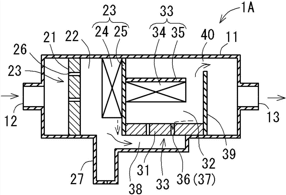
[0053]Next, an oil mist separator according to a second embodiment of the present invention will be described. The oil mist separator of the second embodiment is the same as the oil mist separator 1A of the first embodiment in that it includes two stages of oil separation parts and includes one oil discharge pipe, but the installation position of the oil discharge pipe and the like are different.
[0054] exist Figure 5 Among them, the housing 11 of the oil mist separator 1B is divided into the first partition wall 21 on the upstream side due to the first partition wall 21 on the upstream side in the vertical direction and the second partition wall 31 on the downstream side in the same vertical direction. chamber 22 and the second chamber 32 on the downstream side. The oil separator is formed by arranging the first oil separator 23 upstream of the first chamber 22 and the second oil separator 33 downstream of the second chamber 32 in a row along the blow-by gas flow directio...
no. 3 approach
[0061] Next, an oil mist separator according to a third embodiment of the present invention will be described. The oil mist separator of the third embodiment has two stages of oil separation parts similarly to the oil mist separators of the first and second embodiments, but differs in that two oil discharge pipes are provided.
[0062] exist Image 6 In the same manner as in the second embodiment, the housing 11 of the oil mist separator 1C is divided by providing a first partition wall 21 in the vertical direction on the upstream side and a second partition wall 31 in the vertical direction on the downstream side inside. The first chamber 22 on the upstream side and the second chamber 32 on the downstream side are divided. The oil separator is configured by arranging the first oil separator 23 upstream of the first chamber 22 and the second oil separator 33 downstream of the second chamber 32 in a row along the flow direction of the blow-by gas. Moreover, each oil separatio...
PUM
 Abstract
Description
Claims
Application Information
 - R&D
- Intellectual Property
- Life Sciences
- Materials
- Tech Scout
- Unparalleled Data Quality
- Higher Quality Content
- 60% Fewer Hallucinations
Browse by: Latest US Patents, China's latest patents, Technical Efficacy Thesaurus, Application Domain, Technology Topic, Popular Technical Reports.
© 2025 PatSnap. All rights reserved.Legal|Privacy policy|Modern Slavery Act Transparency Statement|Sitemap|About US| Contact US: help@patsnap.com


