
Drainage pipe and dehumidifier

A drainage pipe and dehumidifier technology, applied in the field of structures and dehumidifiers, can solve the problems of high air outlet temperature of the condenser, affecting user safety and equipment service life, etc., to reduce the air outlet temperature, facilitate batch products and applications, and reduce The effect of workload

Inactive Publication Date: 2018-05-08
GREE ELECTRIC APPLIANCES INC
View PDF5 Cites 3 Cited by
  • Summary
  • Abstract
  • Description
  • Claims
  • Application Information

AI Technical Summary

Problems solved by technology

[0004] In order to solve the technical problem that the air outlet temperature of the condenser of the existing dehumidifier is too high, which affects the safety of the user and the service life of the equipment, the present invention proposes a drain pipe structure for the condensed water of the evaporating fin heat exchanger and the dehumidifier

Method used


Image

  • Drainage pipe and dehumidifier
  • Drainage pipe and dehumidifier
  • Drainage pipe and dehumidifier

Examples


Embodiment 1

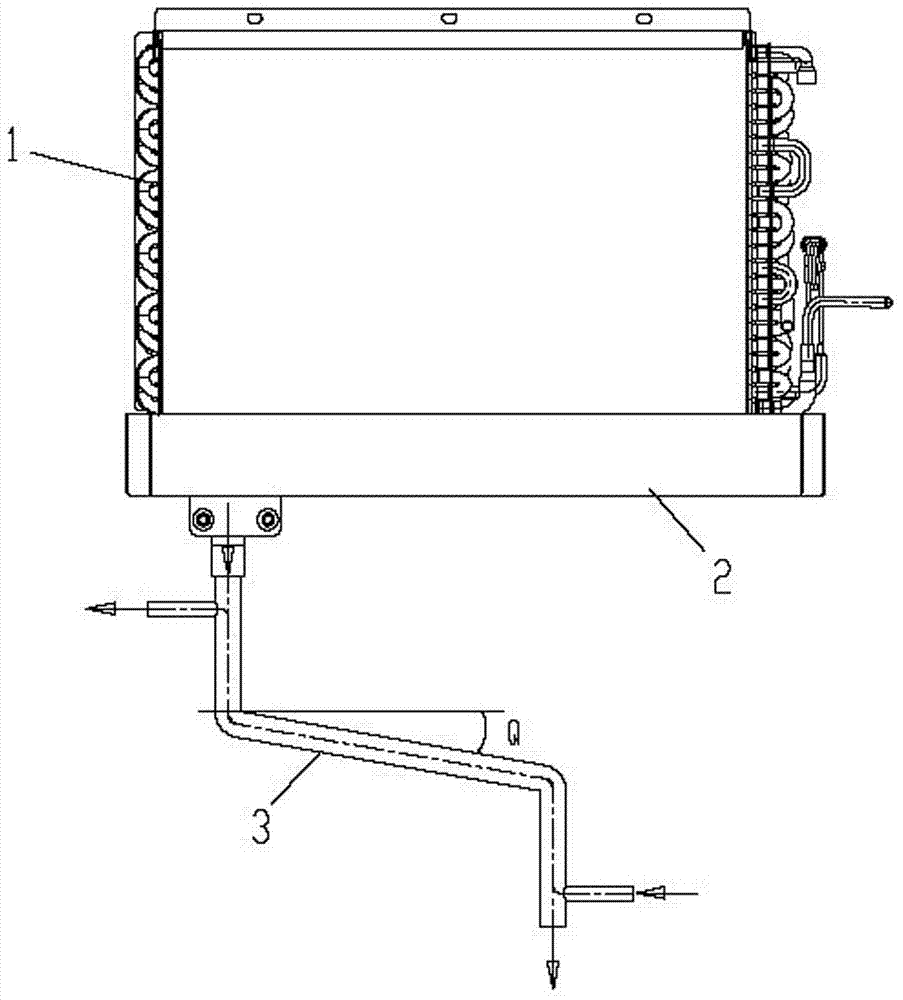
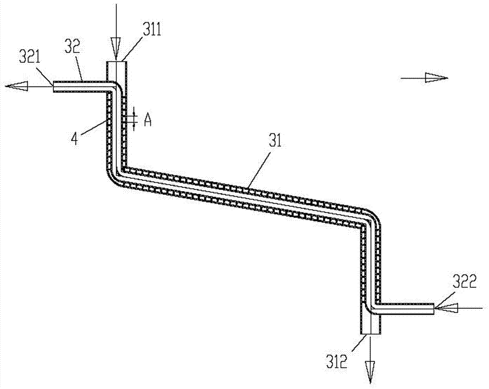
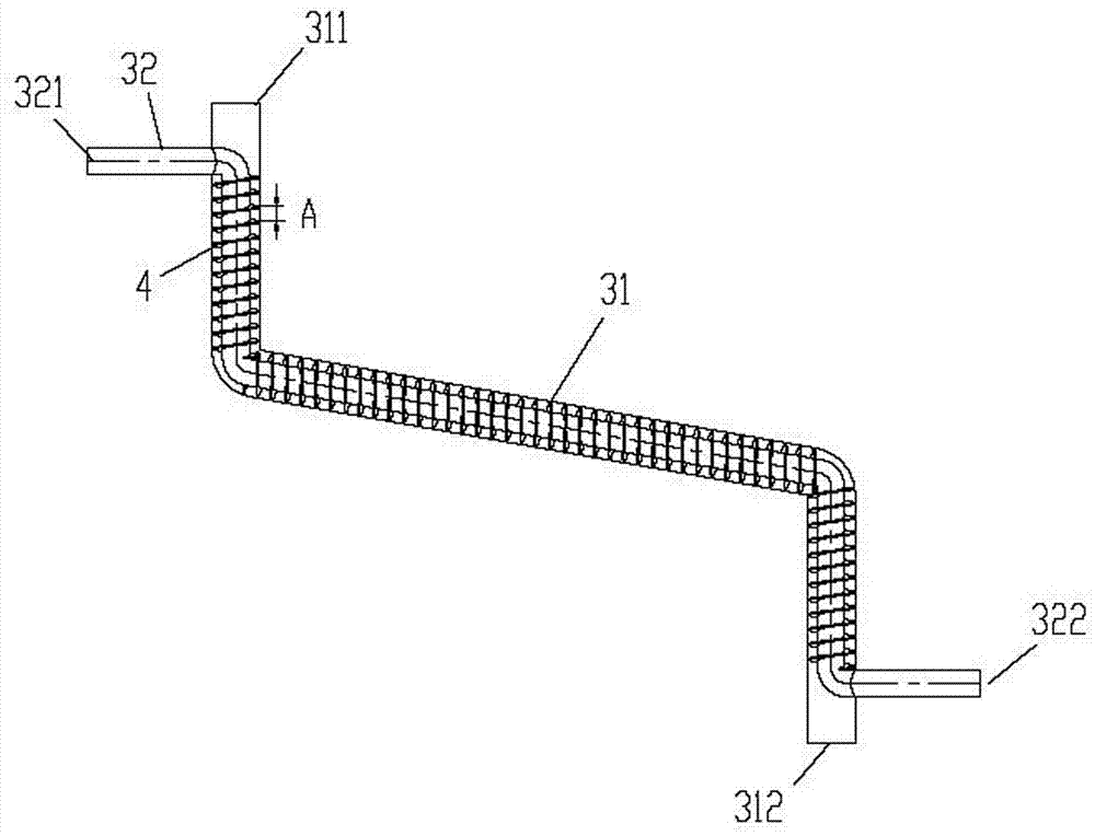
[0026] Embodiment 1, the inlet 311 of the outer layer pipe 31 of the drain pipe is connected to the water receiving tray 2 of the evaporation heat exchanger 1, one port of the inner layer pipe 32 is connected to the exhaust pipe of the compressor, and the other end of the inner layer pipe 32 One port is connected with the intake pipe of the condensing heat exchanger. Specifically, there are two structures: figure 1 As shown, the lower port 322 of the inner pipe 32 can be connected to the discharge pipe of the compressor, and the upper port 321 of the inner pipe 32 can be connected to the intake pipe of the condensing heat exchanger. Then the flow direction of the liquid in the inner layer pipe 32 and the outer layer pipe 31 is opposite. Another structure is: the upper port 321 of the inner layer pipe 32 can be connected with the exhaust pipe of the compressor, and then the lower port 322 of the inner layer pipe 32 can be connected with the intake pipe of the condensing heat e...

Embodiment 2

[0027] Embodiment 2, the inlet 321 of the inner layer pipe 32 of the drain pipe is connected with the water receiving tray 2 of the evaporation heat exchanger 1, one port of the outer layer pipe 31 is connected with the exhaust pipe of the compressor, and the other end of the inner layer pipe 32 One port is connected with the intake pipe of the condensing heat exchanger. Specifically, there are two structures: the lower port 312 of the outer pipe 31 can be connected to the discharge pipe of the compressor, and the upper port 311 of the outer pipe 31 can be connected to the inlet pipe of the condensing heat exchanger. That is, the flow direction of the liquid in the inner pipe 32 and the outer pipe 31 is opposite. Another structure is: the upper port 311 of the outer layer pipe 31 can be connected with the discharge pipe of the compressor, and the lower port 312 of the outer layer pipe 31 can be connected with the inlet pipe of the condensing heat exchanger. That is, the liqui...


PUM


Abstract

The invention discloses a drainage pipe and a dehumidifier. An inner sleeve structure and an outer sleeve structure are adopted by the drainage pipe, and an inner-layer pipeline and an outer-layer pipe each are provided with inlets and outlets. The drainage pipe structure of the condensate water is divided into the inner-layer pipeline and the outer-layer pipeline, the inner-layer pipeline is connected with the exhaust port of the compressor and is used for circulating a high-temperature refrigerant, and the outer-layer pipeline is connected with a water receiving disc of an evaporation heat exchanger of the dehumidifier for circulating condensed water, so that the high-temperature refrigerant at the exhaust port of the low-temperature condensate water and the high-temperature refrigerantof the exhaust port of the compressor are converged and subjected to heat exchange, the exhaust temperature of the compressor can be effectively reduced, and the working load of the condensation heatexchanger is further reduced. On the premise that any energy consumption is not increased, the discharged energy is reused, and the effect of reducing the air outlet temperature of the condensation heat exchanger is achieved. The drainage pipe is simple in structure and easy to produce and apply in batches.

Description

technical field [0001] The invention relates to the field of air dehumidification equipment, in particular to a structure capable of reducing the outlet air temperature of the dehumidifier and the dehumidifier. Background technique [0002] Humid weather will cause people's discomfort, especially in the south where there are more gloomy and humid days, therefore, air dehumidifiers are widely used. The dehumidifier achieves the effect of air dehumidification through the temperature difference between the lower temperature fin heat exchanger and the higher temperature air, and then generates condensation in the heat exchanger. The working principle of the dehumidifier is to enter the indoor humid air into the air duct through the return air outlet, pass through the evaporating fin heat exchanger and the condensing fin heat exchanger successively, and then discharge it into the environment through the air outlet. Therefore, after the air is heated by the condenser, the tempera...

Claims


Application Information

Patent Timeline
Patent Type & Authority Applications(China)
IPC IPC(8): F24F13/22F24F3/14F24F1/02
Inventor 王传华刘大帅刘金喜邴媛媛
Owner GREE ELECTRIC APPLIANCES INC
Learn More