
Food processor

A food processing machine and material technology, applied in the field of food processing machines, can solve the problems of low pulverization and grinding efficiency, single processing method of food materials, and insufficient taste of food materials, etc., and achieves the effect of speeding up the flow rate and avoiding clogging.

Pending Publication Date: 2018-05-11
GUANGDONG MIDEA CONSUMER ELECTRICS MFG CO LTD +1
View PDF0 Cites 1 Cited by
  • Summary
  • Abstract
  • Description
  • Claims
  • Application Information

AI Technical Summary

Problems solved by technology

[0002] Traditional food processing machines have a single processing method for ingredients, the efficiency of crushing and grinding is low, and the taste of ingredients is not delicate enough

Method used


Image

  • Food processor
  • Food processor
  • Food processor

Examples


Embodiment 1

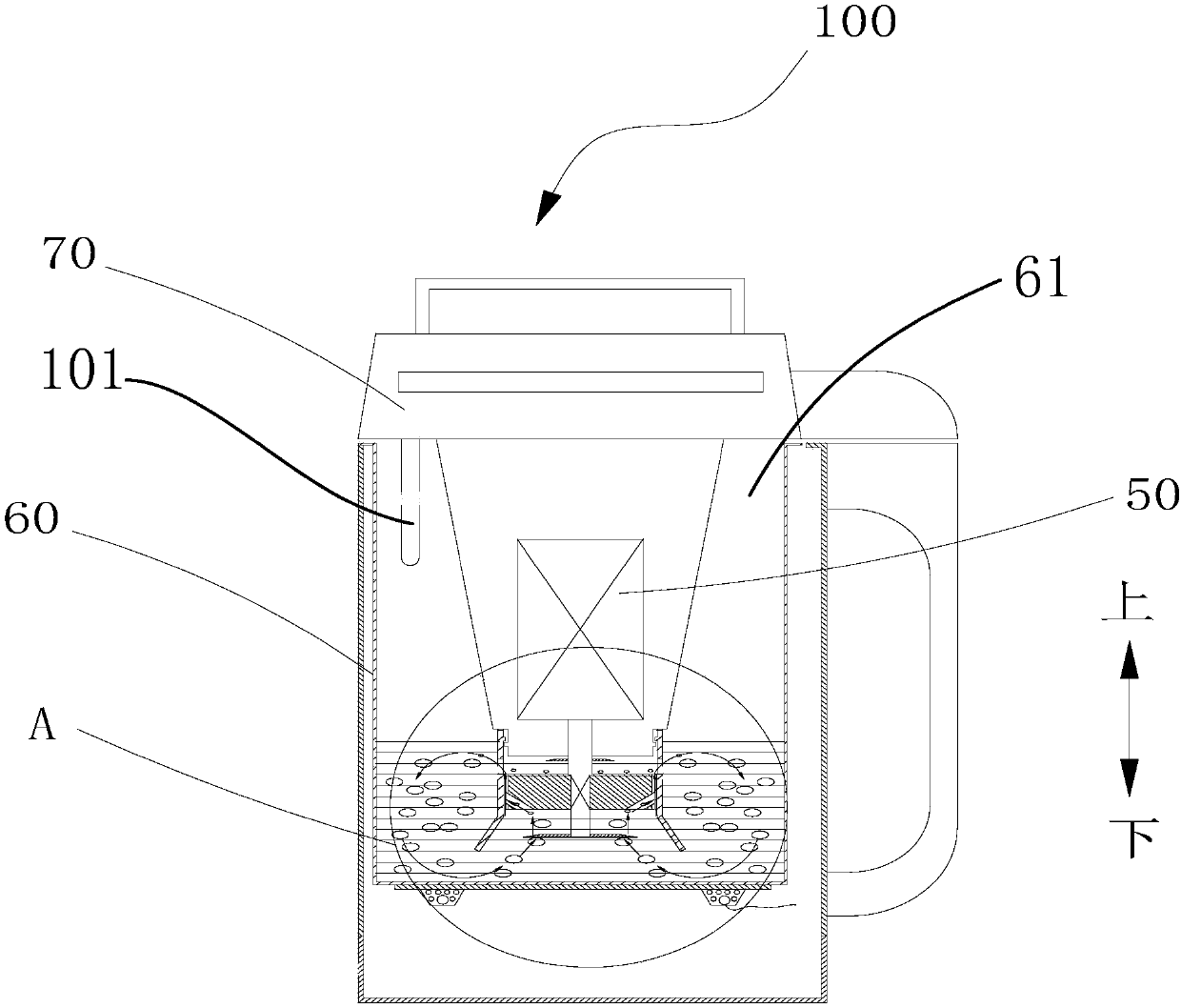
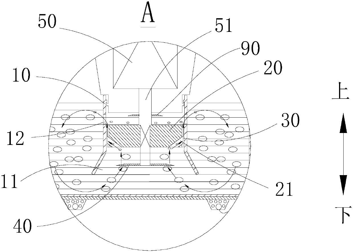
[0086] Embodiment one, such as figure 1 and figure 2 As shown, the food cooking machine may include: a static grinding cover 10 , a dynamic grinding head 20 , a blade 40 , a driving device 50 and an auxiliary pulping blade 90 . Wherein, the driving device 50 is a top-mounted driving motor.

[0087] Specifically, a feeding port 11 and a feeding port 12 arranged at intervals up and down are formed on the static grinding cover 10 . The dynamic grinding head 20 is arranged inside the static grinding cover 10 and is located between the feed port 11 and the discharge port 12 , and a grinding area 30 for grinding materials is defined between the moving grinding head 20 and the static grinding cover 10 . The blade 40 and the movable grinding head 20 are spaced apart in the vertical direction, and the blade 40 is located at the feeding side of the movable grinding head 20 for pulverizing materials. The driving device 50 is respectively connected with the blade 40 and the movable gr...

Embodiment 2

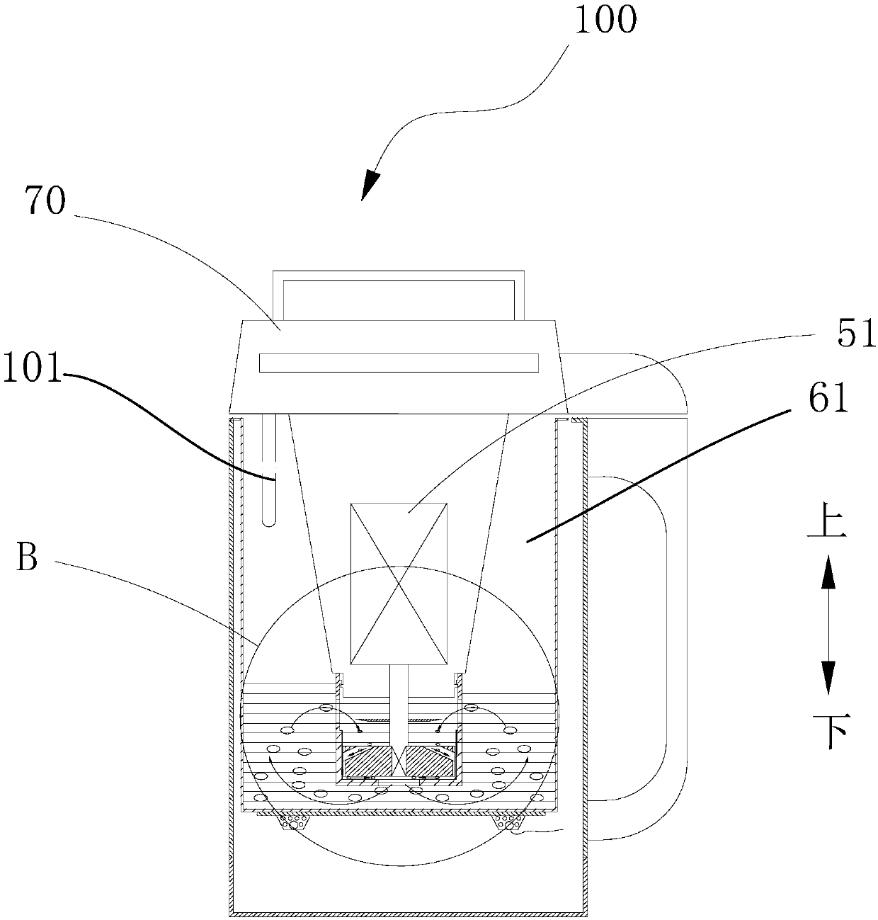
[0102] Embodiment two, such as image 3 and Figure 4 As shown, the food cooking machine 100 may include: a static grinding cover 10 , a dynamic grinding head 20 , a blade 40 and a driving device 50 . Wherein, the driving device 50 is a top-mounted driving motor. The difference between the first embodiment and the second embodiment is that the blade 40 is located above the dynamic grinding head 20 , and the auxiliary pulp discharge blade 90 is not provided on the driving device 50 .

Embodiment 3

[0103] Embodiment three, such as Figure 5 and Figure 6 As shown, the food cooking machine 100 may include: a static grinding cover 10 , a dynamic grinding head 20 , a blade 40 , a driving device 50 and an auxiliary pulping blade 90 . The difference between Embodiment 3 and Embodiment 1 is that the drive device 50 is a bottom-mounted drive motor, the lower end of the static grinding cover 10 is connected to the machine base 80 , and the auxiliary pulp discharge blade 90 is arranged below the dynamic grinding head 20 .


PUM


Abstract

The invention discloses a food processor which comprises a barrel, static grinding covers, moveable grinding heads, blades, auxiliary slurry discharging blades and a driving device, wherein feed portsand discharge ports are formed in the static grinding covers; grinding areas for grinding materials are defined between the moveable grinding heads and the static grinding covers; the grinding areascommunicate with the feed ports and the discharge ports; the blades and the moveable grinding heads are arranged up and down in a spaced manner; the blades are located on the feeding sides of the moveable grinding heads and are used for grinding materials; the auxiliary slurry discharging blades and the moveable grinding heads are arranged up and down in a spaced manner; the auxiliary slurry discharging blades are arranged on the discharge sides of the moveable grinding heads and are opposite to the discharge ports; and the driving device is connected with the blades and the moveable grindingheads so as to drive the moveable grinding heads and the blades to rotate. In the food processor according to the embodiment of the invention, the auxiliary slurry discharging blades are arranged on the discharge sides of the moveable grinding heads so that the flow rate of food materials can be increased, and meanwhile, the food materials are prevented from blocking the discharge sides of the moveable grinding heads under the stirring effect of the auxiliary slurry discharging blades.

Description

technical field [0001] The present invention relates to the technical field of home appliances, and more specifically, to a food cooking machine. Background technique [0002] Traditional food processing machines have a single processing method for ingredients, the efficiency of crushing and grinding is low, and the taste of ingredients is not delicate enough. Contents of the invention [0003] The present invention aims to solve one of the above-mentioned technical problems at least to a certain extent. [0004] Therefore, the present invention proposes a food cooking machine, which can fully pulverize and grind materials, and process food materials with delicate taste. [0005] According to the embodiment of the present invention, the food cooking machine includes: a barrel body, a cover body or a machine head is arranged on the barrel body, an overflow prevention device is arranged on the cover body or the machine head, a crushing and grinding chamber is arranged in th...

Claims


Application Information

Patent Timeline
IPC IPC(8): A47J43/046A47J43/044A47J43/07
CPCA47J43/044A47J43/046A47J43/0711A47J43/0722
Inventor 陈炜杰唐燕
Owner GUANGDONG MIDEA CONSUMER ELECTRICS MFG CO LTD
Learn More