Bone bolt with reinforced anchoring sheets

A technology of bone screws and anchors, applied in the direction of internal bone synthesis, internal fixers, fixers, etc., can solve the problems of poor biomechanical stability of screw fixation, pedicle rupture, damage to important blood vessels, etc., to increase biomechanical stability sexual effect

Inactive Publication Date: 2018-05-11
THE SECOND HOSPITAL AFFILIATED TO WENZHOU MEDICAL COLLEGE
View PDF8 Cites 1 Cited by
  • Summary
  • Abstract
  • Description
  • Claims
  • Application Information

AI Technical Summary

Problems solved by technology

There are some defects when using existing bone screws for fixation: 1) If the fixed bone is cancellous bone or bone abnormality, such as osteoporosis, the anti-pullout and anti-cutting ability of the screw will be weak, and the screw The biomechanical stability of the fixation is poor; 2) If you want to increase the biomechanical stability of the fixation on the basis of the original screw, you generally use bicortical fixation, increase the screw diameter, or inject bone cement into the bone to increase the screw fixation biomechanical strength; but these methods have similar disadvantages, such as injecting bone cement into the bone will cause bone cement leakage, which may damage the surrounding important tissues such as the spinal cord; increasing the screw diameter can enhance the mechanical stability of screw fixation At the same time, it will correspondingly increase bone damage, and some parts cannot be solved by increasing the screw diameter, such as increasing the diameter of the pedicle screw or causing pedicle rupture, which will reduce the biomechanical stability of screw fixation; Double cortex fixation will damage adjacent important structures. For example, if the screw penetrates the anterior cortex of the vertebral body, there is a risk of damaging important blood vessels in front of the vertebral body. potentially life-threatening

Method used


Image

  • Bone bolt with reinforced anchoring sheets
  • Bone bolt with reinforced anchoring sheets
  • Bone bolt with reinforced anchoring sheets

Examples


specific Embodiment 1

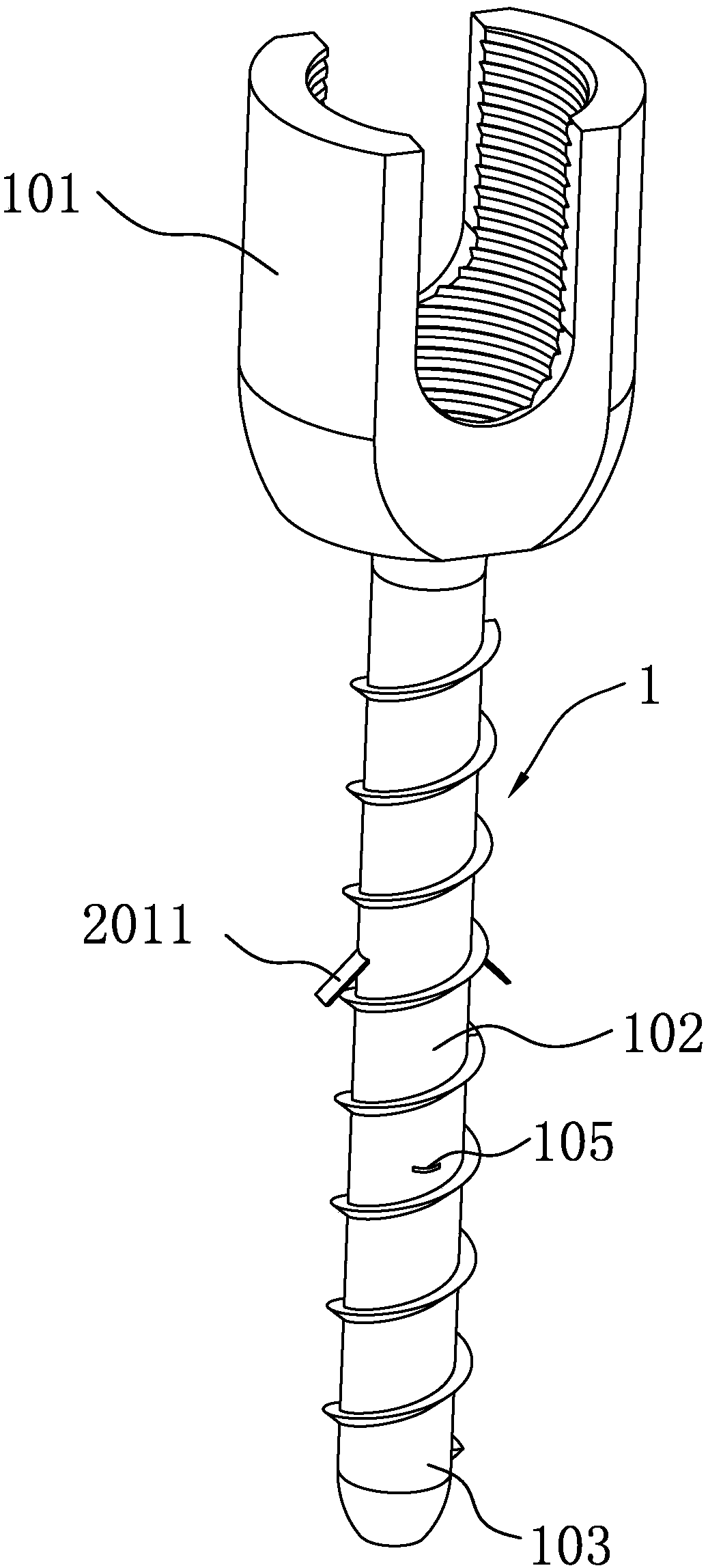
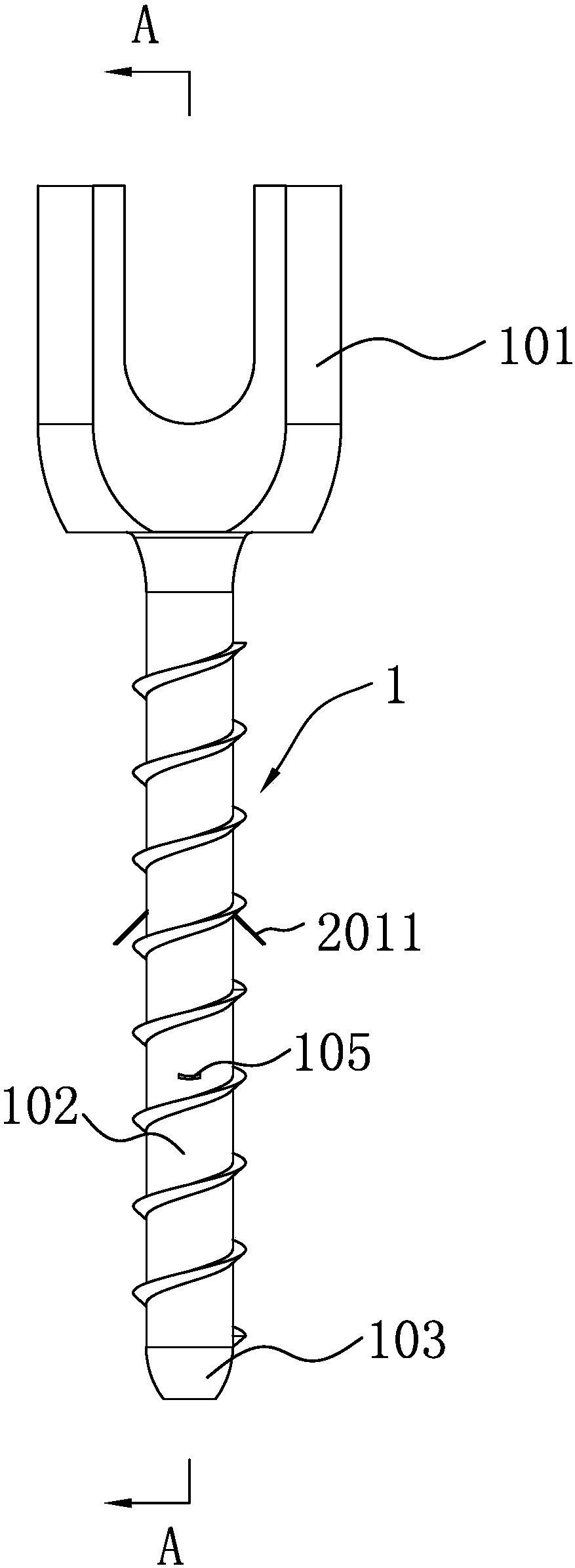
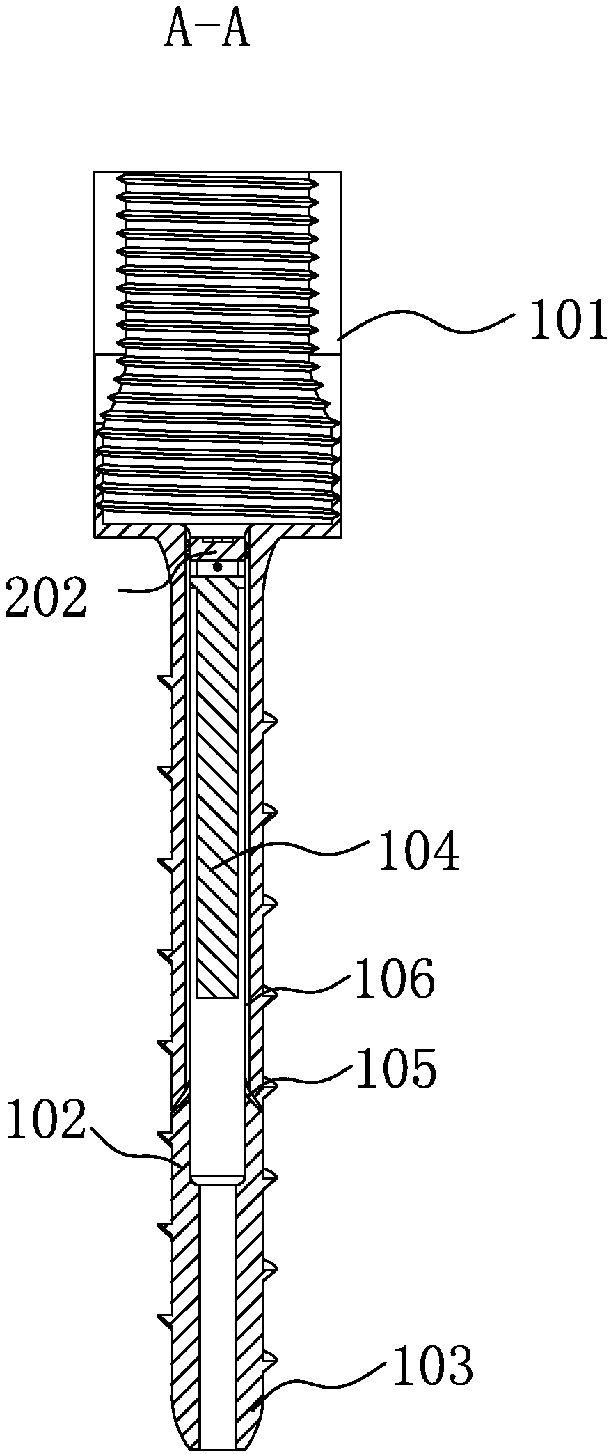
[0024] In this specific embodiment, the screw body 1 includes a nail cap 101, a nail body 102 and a nail point 103, and the nail body 102 and the nail point 103 are provided with threads, and the nail cap 101 is provided with a structure for convenient tool screwing, and the screw The main body 1 is provided with an axial through hole for passing through the guide needle, and the diameter of the through hole near the rear end (one end of the nail cap 101) is slightly larger to form a component cavity 104, and the inner wall of the component cavity 104 is provided with internal threads. A pair of anchor piece slots 105 penetrating through the side wall are obliquely formed on the inner wall of the cavity 104 , and an axial guide groove 106 is provided on the inner wall of the component cavity 104 along the anchor slots 105 to the opening of the component cavity 104 .

[0025] The anchor assembly 2 includes a core rod 201 and a driver 202. The driver 202 is a small section of cyl...

specific Embodiment 2

[0032] In this specific embodiment, the anchor-reinforced bone screw includes a screw body 1 and an anchor assembly 2, and the screw body 1 is provided with an axial through hole for passing through a guide needle, preferably near a part of the rear end (one end of the nail cap 101). The diameter of the through hole is slightly larger to form the component cavity 104 . The anchor piece assembly 2 includes a core rod 201 and a driving member 202, the driving member 202 is set separately from the core rod 201, the driving member 202 is a screw plug that is threadedly connected with the inner wall of the component cavity, and the driving member 202 It is a small section of cylinder whose diameter matches the inner hole of the component cavity 104. The surface of the driving member 202 is provided with an external thread that matches the internal thread, and the rear end surface of the driving member 202 is provided with a slot, which is convenient for tools. By screwing, the driv...


PUM


Abstract

The invention relates to the field of orthopedic surgery machinery, in particular to a bone bolt with reinforced anchoring sheets. The bone bolt includes a bone bolt body and an anchoring sheet assembly, the anchoring sheet assembly includes a core rod and a driving component used for driving the core rod to axially move in an assembly containing cavity, the whole body of the core rod is cylindrical, and a pair of strip-shaped platy components with certain width and suspended front ends obliquely extend outwards, are arranged at the two sides of the core rod and form the anchoring sheets; a pair of anchoring sheet slot holes running through the side walls are obliquely formed in the inner wall of the assembly containing cavity. By driving the driving component and utilizing the screw-thread fit between the driving component and the inner wall of the assembly containing cavity, the driving component is rotated to jack the core rod forward into the assembly containing cavity, the anchoring sheets are pushed to move forwards, and when reaching appropriate positions, the anchoring sheets can extend out of the bolt body along the anchoring sheet slot holes which are obliquely formed andrun through the side walls, so that an anchoring function is achieved. The biomechanical stability effect of bolt fixation can be improved.

Description

technical field [0001] The invention belongs to the field of orthopedic surgical instruments, and in particular relates to a new bone screw---anchor reinforced bone screw. Background technique [0002] In orthopedics, it is often necessary to use screws for internal fixation. When performing orthopedic surgery, screw fixation is a widely used technique. There are some defects when using existing bone screws for fixation: 1) If the fixed bone is cancellous bone or bone abnormality, such as osteoporosis, the anti-pullout and anti-cutting ability of the screw will be weak, and the screw The biomechanical stability of the fixation is poor; 2) If you want to increase the biomechanical stability of the fixation on the basis of the original screw, you generally use bicortical fixation, increase the screw diameter, or inject bone cement into the bone to increase the screw fixation biomechanical strength; but these methods have similar disadvantages, such as injecting bone cement in...

Claims


Application Information

Patent Timeline
Patent Type & Authority Applications(China)
IPC IPC(8): A61B17/68A61B17/86
CPCA61B17/683A61B17/8625A61B17/864A61B17/8685A61B2017/8655
Inventor 林仲可吴龙戚方舟
Owner THE SECOND HOSPITAL AFFILIATED TO WENZHOU MEDICAL COLLEGE
Why Eureka
Try Eureka