
Mixing clarifying tank

A technology of mixing and settling tanks and settling tanks, applied in the field of liquid-liquid extraction, can solve problems such as material density difference and the influence of clarification chamber interface, and achieve the effect of reducing flow resistance

Pending Publication Date: 2018-05-11
CHINA NUCLEAR POWER ENG CO LTD
View PDF6 Cites 5 Cited by
  • Summary
  • Abstract
  • Description
  • Claims
  • Application Information

AI Technical Summary

Problems solved by technology

For the former, it is inevitable to use pumps, valves and pipelines, while for the latter, its application is limited by the difference in material density, and the interface of the clarification chamber is also easily affected by other stages.

Method used


Image

  • Mixing clarifying tank
  • Mixing clarifying tank
  • Mixing clarifying tank

Examples


Embodiment Construction

[0058] The present invention will be further described below in conjunction with the accompanying drawings and embodiments.

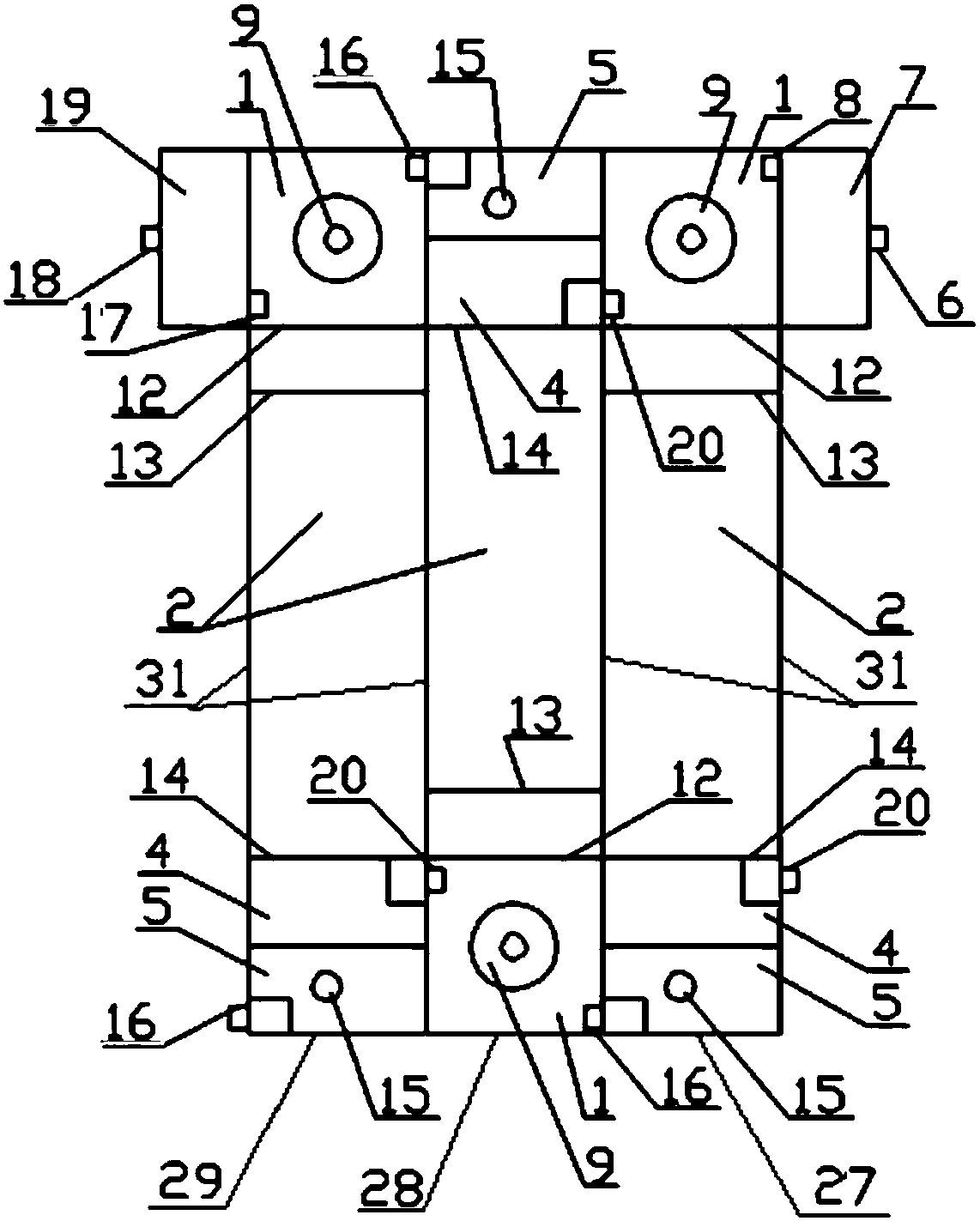
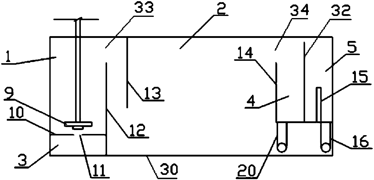
[0059] A kind of mixing clarification tank provided by the present invention comprises at least one clarification tank, consists of mixing chamber 1, clarification chamber 2, submerged chamber 3, light phase small chamber 4, heavy phase small chamber 5, pump wheel 9, heavy phase inlet chamber 7 (heavy phase inlet chamber 7) The phase inlet chamber 7 is provided with a heavy phase inlet 6), and the light phase inlet chamber 19 (the light phase inlet chamber 19 is provided with a light phase inlet 18).

[0060] Such as figure 2 As shown, the clarification chamber 2 is located in the middle of the clarification tank, the mixing chamber 1 and the latent chamber 3 are arranged at one end of the clarification chamber 2, and the light phase chamber 4 and the heavy phase chamber 5 are arranged at the other end of the clarification chamber 2;

[0061] The subm...


PUM


Abstract

The invention belongs to the technical field of liquid-liquid extraction, and specifically relates to a mixing clarifying tank. The mixing clarifying tank comprises at least a clarifying tank; the clarifying tank comprises a clarifying chamber with a mixing chamber and a submerging chamber at one end and a light-phase small chamber and a heavy-phase small chamber at the other end; the submerging chamber is positioned at the lower part of the mixing chamber; a light phase and a heavy phase enter the mixing chamber from the submerging chamber, and are stirred into a mixed phase, and the mixed phase is conveyed to the clarifying chamber; the clarifying chamber is used for separating the mixed phase into a light phase and a heavy phase; the light phase and the heavy phase are respectively conveyed into a light-phase small chamber and a heavy-phase small chamber; the light phase and the heavy phase flow out of the clarifying tank from the light-phase small chamber and the heavy-phase smallchamber; the heavy-phase small chamber can adjust the interface height between the light phase and the heavy phase in the clarifying chamber; when the mixing clarifying tank comprises a plurality of clarifying tanks, the submerging chamber of each clarifying tank can also be connected with the heavy-phase small chamber of an upper-stage clarifying tank and the light-phase small chamber of a next-stage clarifying tank, so that the mixing clarifying tank can be expanded into a multi-stage mixing clarifying tank.

Description

technical field [0001] The invention belongs to the technical field of liquid-liquid extraction, and in particular relates to a mixing and settling tank. Background technique [0002] According to the characteristics of the task and the characteristics of the processing objects, different companies have developed mechanical stirring mixing and settling tanks with different structures. Usually, the stirring device of the mixing and settling tank only plays the role of mixing and stirring the immiscible two-phase, and the material flow depends on pumping, or relies on the driving force formed by the density difference, liquid level difference and interface difference between different materials to overcome the flow resistance. For the former, it is inevitable to use pumps, valves and pipelines, while for the latter, its application is limited by the difference in material density, and the interface of the clarification chamber is also easily affected by other stages. The stir...

Claims


Application Information

Patent Timeline
IPC IPC(8): B01D11/04
CPCB01D11/0457
Inventor 刘继连李少伟景山侯留东高明媛史惠杰杨浩李硕
Owner CHINA NUCLEAR POWER ENG CO LTD
Learn More