Clamp for detecting of automobile covering part

A technology of automobile covering parts and fixtures, which is applied in the field of machinery, can solve the problems of inability to make fine adjustments, lack of shock-absorbing devices, and low degree of automation, and achieve the effects of simple structure, convenient clamping work, and high degree of automation

Inactive Publication Date: 2018-05-11
柳州市钜嘉机械有限公司
View PDF5 Cites 15 Cited by
  • Summary
  • Abstract
  • Description
  • Claims
  • Application Information

AI Technical Summary

Problems solved by technology

[0003] At present, the existing clamps have great disadvantages in the clamping process. They cannot be finely adjusted, and the clamping accuracy is low, and most of them are manually clamped, which has a low degree of automation and low work efficiency. Some fixtures do not have a shock-absorbing device, which is easy to cause damage to the cover and cause economic losses when performing clamping inspections on automobile panels. Therefore, we propose a fixture for automobile panel inspection to solve the above problems

Method used


Image

  • Clamp for detecting of automobile covering part
  • Clamp for detecting of automobile covering part
  • Clamp for detecting of automobile covering part

Examples


Embodiment 1

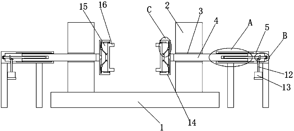
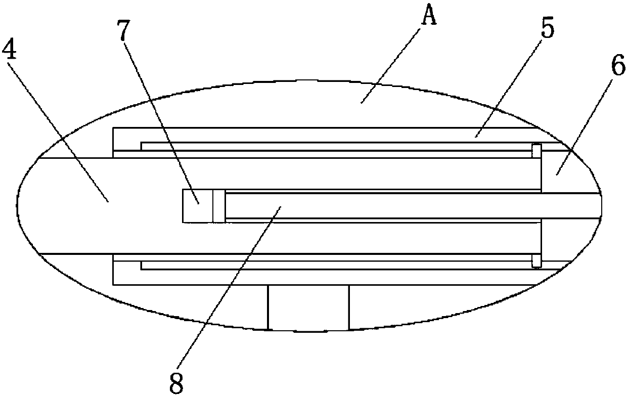
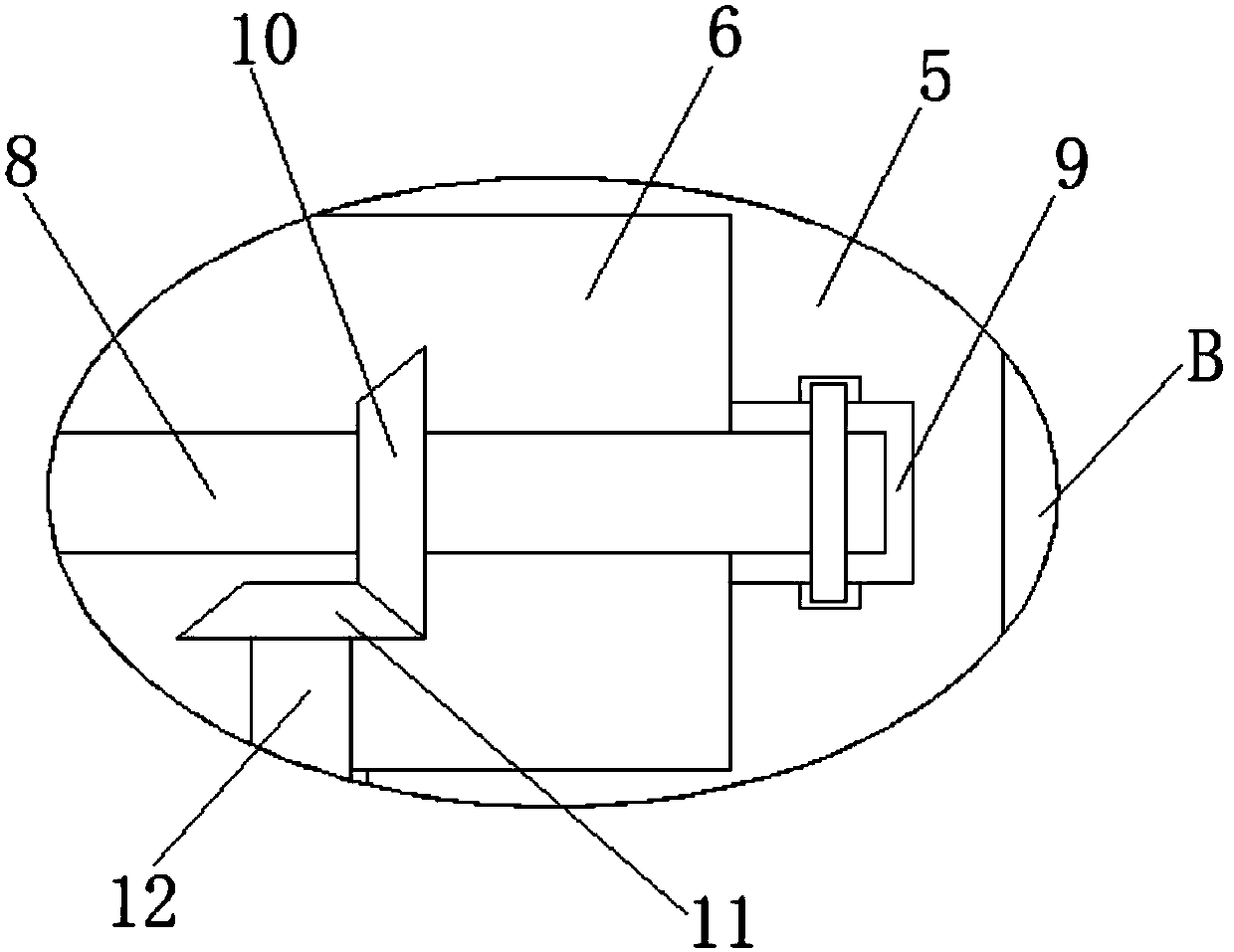
[0027] refer to Figure 1-5, a kind of jig for automobile cover detection, comprising a fixed seat 1, two fixed rods 2 are welded on the top of the fixed seat 1, a connecting rod through hole 3 is opened on the fixed rod 2, and a connecting rod through hole 3 is slidably installed with a connecting rod. rod 4, and both ends of the connecting rod 4 are extended to the outside of the connecting rod through hole 3, both sides of the fixing seat 1 are provided with a fixing block 5, and the side of the fixing block 5 close to the fixing rod 2 is provided with a connecting rod groove 6, The connecting rod groove 6 is slidingly connected with the connecting rod 4, and one end of the connecting rod 4 extends to the outside of the connecting rod groove 6, and the connecting rod 4 is provided with a rotating shaft groove 7 on one side in the connecting rod groove 6, and the rotating shaft groove 7 is installed There is a first rotating shaft 8, and one end of the first rotating shaft 8...

Embodiment 2

[0031] refer to Figure 1-5 , a kind of jig for automobile cover detection, comprising a fixed seat 1, the top of the fixed seat 1 is provided with a welding sleeve, and the top of the fixed seat 1 is welded with two fixed rods 2 through the welding sleeve, so that the fixed rods are firmly welded on the On the fixed seat, the fixed rod 2 is provided with a connecting rod through hole 3, and the connecting rod 4 is slidably installed in the connecting rod through hole 3, and the two ends of the connecting rod 4 all extend to the outside of the connecting rod through hole 3, and the fixed seat 1 Both sides are provided with a fixed block 5, and the side of the fixed block 5 close to the fixed rod 2 is provided with a connecting rod groove 6, the connecting rod groove 6 is slidingly connected with the connecting rod 4, and one end of the connecting rod 4 extends to the connecting rod groove 6 Outside, connecting rod 4 is positioned at the side in connecting rod groove 6 and is p...


PUM


Abstract

The invention discloses a clamp for detecting of an automobile covering part. The clamp comprises a fixing seat, wherein two fixing rods are welded to the top end of the fixing seat; a connecting rodthrough hole is formed in each fixing rod; connecting rods are mounted into the connecting rod through holes in a sliding manner, and two ends of the connecting rods extend out of the connecting rod through holes; fixing blocks are arranged at two sides of the fixing seat; a connecting rod groove which is in sliding connection with each connecting rod is formed in one side, close to the corresponding fixing rod, of each fixing block; one end of each connecting rod extends out of the corresponding connecting rod groove; a rotating shaft groove is formed in one side, in the corresponding connecting rod groove, of each connecting rod; first rotating shafts are rotatably mounted in the rotating shaft grooves. The clamp is simple in structure, and convenient to use; the clamping accuracy of theclamp is improved; the fine adjusting can be carried out, so that the clamping work can be conveniently performed; the automation degree is high; the clamp is capable of damping, so that the damage to the automobile covering part is reduced; the time is saved; and the working efficiency is improved.

Description

technical field [0001] The invention relates to the technical field of machinery, in particular to a jig for testing automobile cover parts. Background technique [0002] Automobile cover parts refer to the surface or internal parts of the space shape made of thin metal plates that cover the engine, chassis, cab, and body. They have different characteristics from general stamping parts in terms of process design, mold processing, equipment selection and quality control. [0003] At present, the existing fixtures have great disadvantages in the clamping process. They cannot be finely adjusted, and the clamping accuracy is low, and most of them are manually clamped, which has a low degree of automation and low work efficiency. There are jigs without shock-absorbing devices, which are easy to cause damage to the car cover and cause economic losses when clamping and testing the car cover. Therefore, we propose a jig for car cover testing to solve the above problems . Content...

Claims


Application Information

Patent Timeline
Patent Type & Authority Applications(China)
IPC IPC(8): B25B11/00G01M17/00
CPCB25B11/00G01M17/00
Inventor 王小华梁程鹏
Owner 柳州市钜嘉机械有限公司
Why Eureka
Try Eureka