Push mechanism for industrial machinery tire production

A technology of industrial machinery and push mechanism, which is applied in the direction of conveyor objects, transportation and packaging, and cleaning devices, etc., which can solve the problems of increased production costs, poor connection stability of the load-carrying frame, and labor-consuming physical strength, so as to increase the carrying capacity and overcome The effect of unstable connection

Inactive Publication Date: 2018-05-11
余浙奇
View PDF1 Cites 0 Cited by
  • Summary
  • Abstract
  • Description
  • Claims
  • Application Information

AI Technical Summary

Problems solved by technology

[0002] In the process of tire production and processing, there is a link of material feeding. The most traditional method before is manual feeding, but such people consume more physical strength of the laborers, and the work efficiency is extremely slow, which increases the production cost. After that, people The feeding machine has been produced, but the raw materials on the traditional feeding machine are likely to be separated from the drive shaft during transportation, so the staff needs to monitor the whole process, which will bring unnecessary trouble to the staff
At the same time, it is also possible that there is a shortage of raw materials, and the personnel did not add new raw materials in time, which will affect the operation of the subsequent processing machines. In the prior art, for example, the invention patent with the application number 201220463170.X includes the frame and the motor. The frame is provided with a drive shaft, and the drive shaft is connected to the motor through a drive chain. One side of the frame is provided with a bearing plate, and both sides of the load plate are respectively provided with retaining columns. The other side of the frame is also provided with a binder frame. Although the invention is simple in structure, there are many deficiencies and defects. In the existing equipment, the design of the carrier frame has defects, the connection stability of the carrier frame is poor, and the tires are placed on the frame. When the material is not blocked by the blocking column when moving up, the raw material will fall, and the pressing frame is not equipped with a device to prevent the material from falling. In view of these situations, in order to avoid the above technical problems, it is necessary to provide a tire for industrial machinery production. Push mechanism to overcome said drawbacks in the prior art

Method used


Image

  • Push mechanism for industrial machinery tire production
  • Push mechanism for industrial machinery tire production
  • Push mechanism for industrial machinery tire production

Examples


Embodiment Construction

[0023] The following will clearly and completely describe the technical solutions in the embodiments of the present invention with reference to the accompanying drawings in the embodiments of the present invention. Obviously, the described embodiments are only some, not all, embodiments of the present invention. Based on the embodiments of the present invention, all other embodiments obtained by persons of ordinary skill in the art without making creative efforts belong to the protection scope of the present invention.

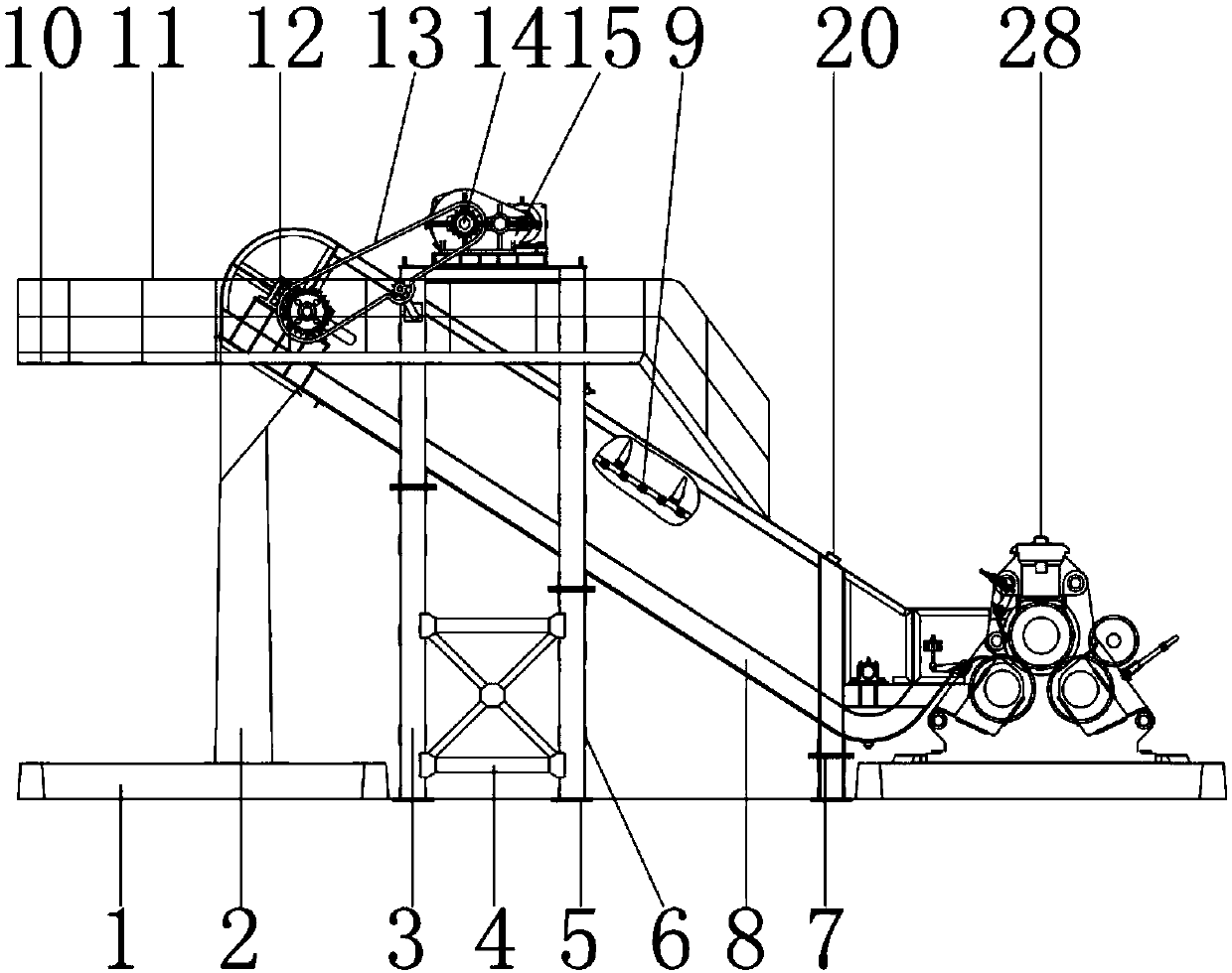
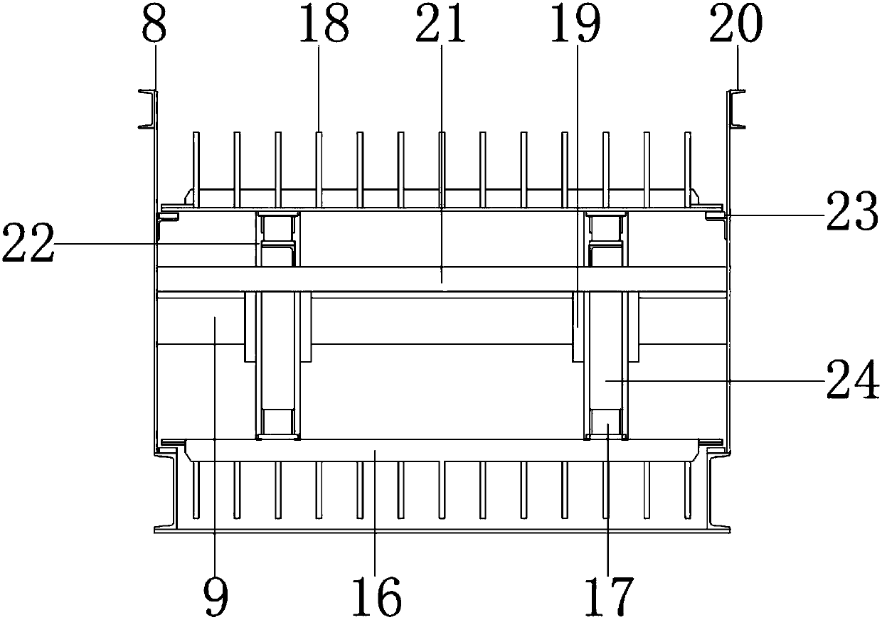
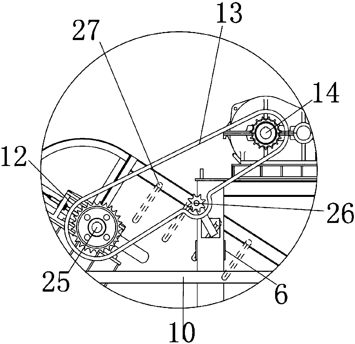
[0024] see Figure 1-4, the present invention provides a technical solution: a push mechanism for industrial machinery tire production, including a base 1, the material of the base 1 is stainless steel, used to fix the column 2, the upper surface of the base 1 is provided with a base 31, the base The seat 31 is used to connect and fix the bottom bar 30. The upper surface of the base 31 is provided with the bottom bar 30. The bottom bar 30 is made of stainless ...


PUM


Abstract

The invention discloses a push mechanism for industrial machinery tire production. Stand columns are arranged on a base. The lower surfaces of the stand columns are connected with the upper surface ofthe base. Side plates are arranged above the stand columns. The lower surfaces of the side plates are connected with the upper surfaces of the stand columns. Supporting legs are arranged on the rightside of the stand columns. According to the tire production pushing mechanism for the industrial machinery, through cooperation of a first motor, a second motor and scraping plates, and under the action of the motors, the motors drive conveying rolls to rotate and transport tires. During rotating, the speed of the conveying rolls can be increased by adjusting the rotating speed of the motors andthen the rotating speed of the conveying rolls can be increased, so that tires are driven and conveyed upwards; in order to prevent the tires from falling off from the two sides during upward moving,guard rail vertical plates and guard rail transverse plates are mounted on the two sides of the side plates. Accordingly, the defect that a traditional push mechanism for industrial machinery tire production is low in tire distribution efficiency and tires fall off in the distribution process is avoided.

Description

technical field [0001] The invention relates to the technical field of tire production, in particular to a pushing mechanism for industrial machinery tire production. Background technique [0002] In the process of tire production and processing, there is a link of material feeding. The most traditional method before is manual feeding, but such people consume more physical strength of the laborers, and the work efficiency is extremely slow, which increases the production cost. After that, people A feeding machine has been produced, but the raw materials on the traditional feeding machine are likely to be separated from the transmission shaft during transportation, so the staff needs to monitor the whole process, which will bring unnecessary trouble to the staff. At the same time, it is also possible that there is a shortage of raw materials, and the personnel did not add new raw materials in time, which will affect the operation of the subsequent processing machines. In the ...

Claims


Application Information

Patent Timeline
IPC IPC(8): B65G13/00B65G47/82B65G45/12
CPCB65G13/00B65G45/12B65G47/82
Inventor 余浙奇
Owner 余浙奇
Why Eureka
Try Eureka