
Method for improving process of displacement gas of reactor of continuous reformer

A reforming device and reactor technology, which is applied in the petroleum industry, naphtha treatment, etc., can solve problems such as excessive discharge of non-methane hydrocarbons, deteriorating operating conditions, regeneration air release, catalyst oil affecting lifting and transportation, etc., to achieve The effect of improving the operating conditions and reducing the hidden danger of overheating

Inactive Publication Date: 2018-05-11
SINOPEC GUANGZHOU ENG +1
View PDF5 Cites 0 Cited by
  • Summary
  • Abstract
  • Description
  • Claims
  • Application Information

AI Technical Summary

Problems solved by technology

[0007] The purpose of the present invention is to provide an improved method for the replacement gas flow process of the reactor of a continuous reforming unit. The replacement gas is changed from circulating hydrogen to gas source hydrogen containing less hydrocarbons, so as to solve the purging effect of more hydrocarbons in the circulating hydrogen Not good, causing the oil in the catalyst to affect the lifting and transportation; the operating condition of the chlorine absorption section or the chlorine absorption tank of the standby catalyst tends to deteriorate, and the carrying of hydrocarbons causes technical problems such as excessive emissions of non-methane hydrocarbons in the regeneration venting air

Method used


Image

  • Method for improving process of displacement gas of reactor of continuous reformer
  • Method for improving process of displacement gas of reactor of continuous reformer

Examples


Embodiment Construction

[0022] The present invention will be further explained below in conjunction with the drawings:

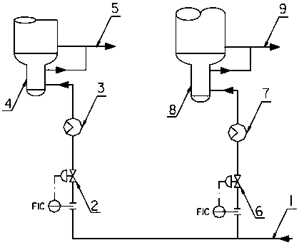
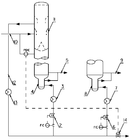
[0023] As attached figure 1 As shown, the gas source hydrogen 1 with less hydrocarbon content introduced from the device is divided into two strands. One strand is used as the replacement gas of the No. 1 reactor and is adjusted by the No. 1 reactor replacement gas flow control valve 2 and then passed through the No. 1 reactor. The replacement gas heat exchanger 3 exchanges heat to 120-140°C, and enters the second reactor catalyst collector 4 to purge the oil and gas on the catalyst under its own weight from the second reactor, and the catalyst that blows off the oil and gas is upgraded to the third reactor buffer In section, the replacement gas enters the second intermediate heating furnace along with the reaction product 5 of the second reactor. One is used as the replacement gas of the second reactor to be adjusted by the replacement gas flow control valve 6 of the second reactor, ...


PUM


Abstract

The invention discloses a method for improving a process of a displacement gas of a reactor of a continuous reformer. The displacement gas is changed from circulating hydrogen to gas-source hydrogen containing less hydrocarbon substances so as to solve the technical problems that lifting and transportation are influenced by a catalyst with oil caused by poor purging effects of the circulating hydrogen due to many hydrocarbon substances in the circulating hydrogen; and non-methane hydrocarbons in a regenerated vent gas exceed the standards because a chlorine absorption section or a chlorine absorption tank of the spent catalyst tend to deterioration in operating conditions and has the hydrocarbon substances.

Description

Technical field [0001] The invention belongs to the field of petrochemical technology, and specifically relates to a method for improving the replacement gas flow of a continuous reformer reactor. Background technique [0002] In the prior art of continuous reforming, the reformed circulating hydrogen (recycled gas) is used as the replacement gas to blow off most of the oil and gas from the catalyst to facilitate the upgrading and transportation of the catalyst. However, because the reformed circulating hydrogen contains more hydrocarbons, the corresponding In the continuous catalyst regeneration process, hydrocarbons are carried along with the catalyst to the chlorine absorption section or chlorine absorption tank. This method of using circulating hydrogen as the replacement gas also brings some problems, specifically: [0003] First, the hydrocarbons are discharged with the regeneration vent, causing the non-methane hydrocarbons in the regeneration vent to exceed the emission sta...

Claims


Application Information

Patent Timeline
Patent Type & Authority Applications(China)
IPC IPC(8): C10G59/02
CPCC10G59/02
Inventor 徐又春孙秋荣郭劲鹤李爱国董海芳
Owner SINOPEC GUANGZHOU ENG
Learn More