System and method for rapid engine coolant warm-up

A technology of engine cooling and cooling system, which is applied in the direction of engine cooling, coolant flow control, engine components, etc., and can solve problems such as expensive, increasing the complexity of vehicle systems, uneven heating durability, etc.

Active Publication Date: 2022-02-11
FORD GLOBAL TECH LLC
View PDF7 Cites 0 Cited by
  • Summary
  • Abstract
  • Description
  • Claims
  • Application Information

AI Technical Summary

Problems solved by technology

First, stagnating coolant flow in the engine to allow rapid warm-up can lead to durability issues due to uneven heating of various engine components
Furthermore, the use of electronic valves to selectively control the circulation of coolant in the various coolant loops is expensive and adds to the complexity of the vehicle system

Method used


Image

  • System and method for rapid engine coolant warm-up
  • System and method for rapid engine coolant warm-up
  • System and method for rapid engine coolant warm-up

Examples


Embodiment Construction

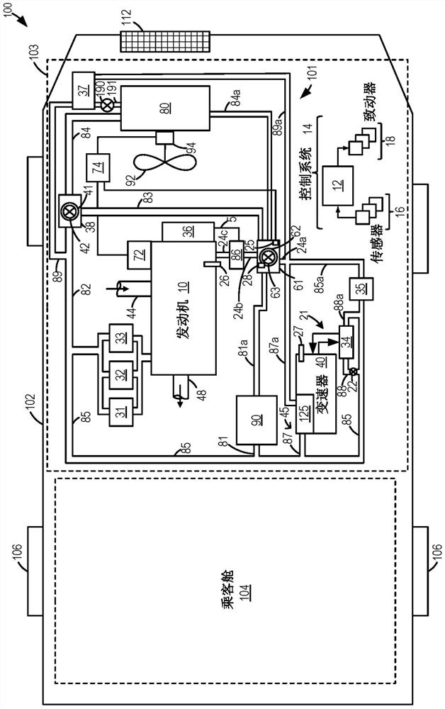
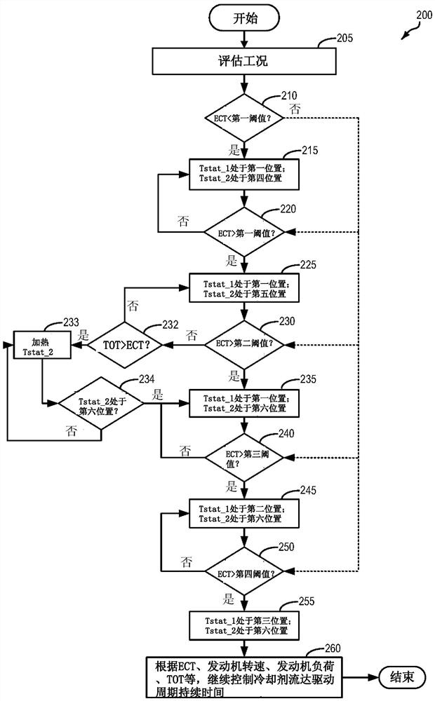
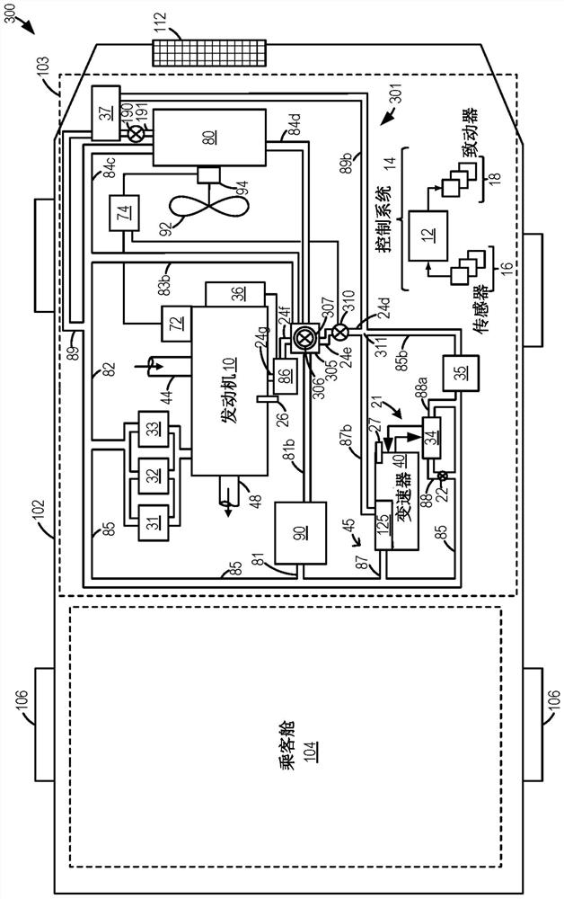
[0017] The following description relates to systems and methods for regulating coolant flow in a vehicle cooling system during an engine start event. In one example, a vehicle cooling system may include two conventional thermostats, wherein a first thermostat may be positioned on the hot side of the vehicle cooling system, and wherein a second thermostat may be positioned on the cold side of the vehicle cooling system, as figure 1 shown. In this example, the second thermostat may comprise an electric heating thermostat. figure 2 shown in the figure 1 Illustrated is the method by which the system controls coolant flow during an engine start event. Briefly, the method may include, under a first condition, responsive to an engine coolant temperature being below a first threshold, flowing coolant through a first thermostatic valve in a first position and in a first position prior to returning to the engine under a first condition. The four position second thermostatic valve is...


PUM


Abstract

The present invention relates to systems and methods for rapid engine coolant warm-up, providing methods and systems for regulating coolant flow in a vehicle cooling system during an engine start event. In one example, a method includes, during an engine start event, controlling a flow path of engine coolant in a vehicle cooling system via a passive valve and an actively adjustable valve, and responding to the engine coolant temperature being below a threshold during the engine start event , to isolate the flow path of the engine coolant to subsections of the cooling system to allow the engine coolant to warm quickly without stagnating the engine coolant at the engine. In this way, the engine coolant can be warmed quickly during an engine start event via coolant flow isolation rather than coolant flow stagnation, which can reduce uneven heating of engine system components and thus extend the functional life of the engine system .

Description

technical field [0001] The present invention generally relates to methods and systems for controlling a vehicle engine to adjust a volume of coolant circulation based on coolant temperature. Background technique [0002] Vehicles may include a cooling system configured to reduce engine overheating by transferring heat to ambient air. Therein, coolant is circulated through the engine block to remove heat from the hot engine, and the heated coolant is then circulated through the radiator near the front of the vehicle. Heated coolant may also be circulated through the heat exchanger to heat the passenger compartment. A cooling system may include various components, such as various valves and one or more thermostats. [0003] While vehicles may include cooling systems to reduce engine overheating, it is also understood that vehicle systems tend to operate most efficiently when in an optimal temperature range. For example, engines operating well above optimum temperatures can ...

Claims


Application Information

Patent Timeline
Patent Type & Authority Patents(China)
IPC IPC(8): F01P7/16
CPCF01P7/165F01P2050/22F01P2007/146F01P7/048F01P7/167F01P2005/125F01P2060/04F01P2060/045F01P2060/16F01P2070/04F01P2023/08F01P2025/40F01P2025/50F01P2037/02F01P2060/08F01P2060/12F01P3/20F01P5/10F01P7/14F01P7/16F01N2610/11F01P2060/18
Inventor J·P·斯泰容
Owner FORD GLOBAL TECH LLC
Why Eureka
Try Eureka