
Marine propeller blade laser automatic measuring device

A marine propeller and automatic measurement technology, which is applied in the direction of measuring devices, optical devices, instruments, etc., can solve the problems of lack of synchronous measurement and comparison of propeller blades, poor processing accuracy, and inaccurate measurement accuracy, etc.

Pending Publication Date: 2018-05-11
ZHENJIANG TONGZHOU PROPELLER
View PDF0 Cites 7 Cited by
  • Summary
  • Abstract
  • Description
  • Claims
  • Application Information

AI Technical Summary

Problems solved by technology

At present, many domestic enterprises have begun to use four-coordinate and five-coordinate CNC milling machines to process marine propellers, and then polish them to a satisfactory accuracy. These are inseparable from the final manual polishing of propellers. Although manual polishing can achieve complex curved surfaces Grinding and polishing, but due to the subjective influence of people, the quality of the curved surface is determined by the proficiency of the operator, so it is impossible to effectively control the dimensional accuracy of the workpiece, resulting in poor processing accuracy and difficult to guarantee the quality of the surface. Therefore, the propeller The accuracy of the blade must be accurately measured, and then readjusted according to the measurement results to ensure the performance of the ship
However, the measurement accuracy of the existing precision measurement devices is not accurate enough, especially the lack of the function of synchronous measurement and comparison of the upper and lower sides of the propeller blades, and the measurement accuracy and measurement level need to be further improved

Method used


Image

  • Marine propeller blade laser automatic measuring device
  • Marine propeller blade laser automatic measuring device
  • Marine propeller blade laser automatic measuring device

Examples


Embodiment Construction

[0018] The specific embodiment of the present invention will be described in further detail below in conjunction with accompanying drawing, in order to have further understanding to the conception of the present invention, the technical problem solved, the technical feature that constitutes the technical solution and the technical effect that brings, it should be noted that , the descriptions of these embodiments are schematic and do not constitute a specific limitation to the present invention.

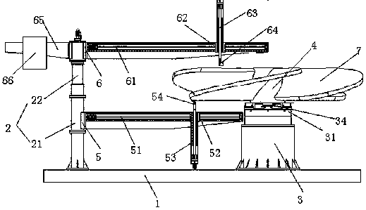
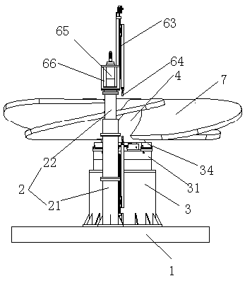
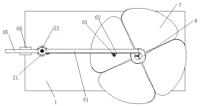
[0019] It can be seen from the figure that the laser automatic measuring device for marine propeller blades is characterized in that it includes a fixed base 1, the fixed base 1 is a rectangular plate structure, and the fixed base 1 is fixedly installed with a lifting fixing rod 2 and a propeller fixing seat respectively. 3. The lifting fixing rod 2 and the propeller fixing seat 3 are symmetrically fixed on the upper end surface of the fixed base 1 respectively, and a motor 31 is fixe...


PUM


Abstract

A marine propeller blade laser automatic measuring device of the invention includes a fixed base; and a lifting and fixing rod and a propeller fixing seat that are mounted at both ends thereof. The propeller fixing seat has a rotating fixed table. A propeller hub is clamped and embedded between inner and outer pressure plates of the fixed table and is driven by an internal motor to rotate. The fixing and lifting rod is driven by an internal cylinder to expand and contract, so as to fit more propeller blade dimensions, two sliding rods are respectively mounted on upper and lower ends thereof, sliding blocks are also slidably mounted on the sliding rods, laser measuring pens are mounted fixedly on the sliding blocks, laser measuring heads of the laser measuring pens are respectively arrangedopposite to each other on upper and lower end surfaces of a propeller blade, and under the drive of a synchronous motor, the sliding blocks slide on the sliding rods to drive the laser measuring heads to move in a radial length of the propeller blade to achieve dynamic measurement. Under the drive of the synchronous motor and the motor in the propeller fixing seat, the measurement automation is fully realized, subjective deviations caused by manual measurement are avoided, the measured data are more accurate and comprehensive, and the measurement accuracy is higher.

Description

technical field [0001] The invention belongs to the technical field of measuring machinery, in particular to a laser automatic measuring device for ship propeller blades. Background technique [0002] Propeller refers to a device that converts the rotational power of the engine into propulsion by rotating the blades in the air or water. There may be two or more blades connected to the hub, and the rear side of the blades is a helical surface or similar to a helical surface. A marine propeller. [0003] The marine propeller is the core component of the ship. It is the most efficient and widely used type of marine propeller. Its main function is to make the ship move forward and backward, and sometimes assist the ship to turn. The performance of a ship depends on the three major factors of the ship's ship type, main engine and propeller. The propulsion efficiency of the propeller mainly depends on the design and manufacture of the propeller blades, so the precision of the pr...

Claims


Application Information

Patent Timeline
IPC IPC(8): G01B11/00
CPCG01B11/00
Inventor 刘红奇徐高峰陈志国梅斌贤宋佩学王湘来
Owner ZHENJIANG TONGZHOU PROPELLER
Learn More