Fully-automatic piston pressure gauge

A piston pressure gauge, fully automatic technology, applied in the field of precision instruments, can solve problems such as low work efficiency and errors, and achieve the effects of improving accuracy and measurement speed, improving efficiency and accuracy, and improving output accuracy

Inactive Publication Date: 2018-05-11
赵珊珊
View PDF0 Cites 23 Cited by
  • Summary
  • Abstract
  • Description
  • Claims
  • Application Information

AI Technical Summary

Benefits of technology

This technology allows for an automated way to measure things accurately by automatically moving sensors around while keeping them under control during measurements. It also includes features like electric motors that move or vibrate the devices instead of manually pushing it upwardly towards each other when they're being measured. Overall this helps make better quality inspections faster than traditional methods.

Problems solved by technology

The technical problem addressed by this patented method is that current manual operation methods can lead people into errors or reduce their productivity due to lack of automated systems designed specifically for these types of measurements.

Method used


Image

  • Fully-automatic piston pressure gauge
  • Fully-automatic piston pressure gauge

Examples


Embodiment Construction

[0014] The following will clearly and completely describe the technical solutions in the embodiments of the present invention with reference to the drawings in the embodiments of the present invention.

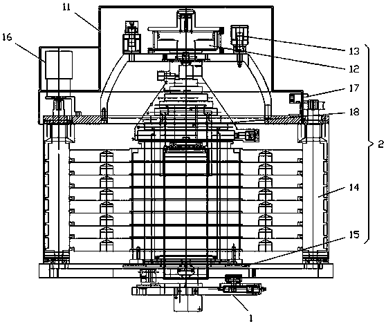
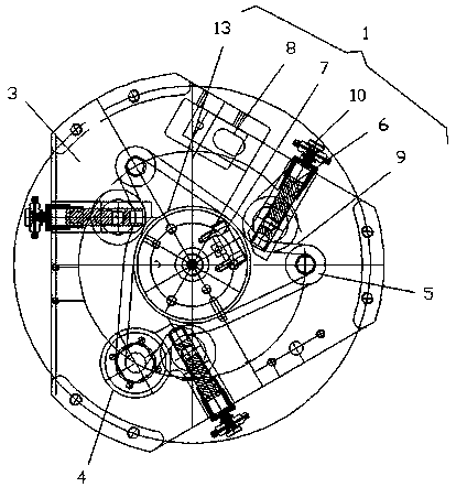
[0015] see Figure 1-2 , the present invention provides a technical solution: a fully automatic piston pressure gauge, comprising a piston rotation system 1 and a weight selection system 2, the piston rotation system 1 is located at the bottom of the weight selection system 2; the piston rotation system 1 Including a base 3, a motor 4, a pulley 5, a piston 6, a speed sensor 7 and a displacement sensor 8, the surface of the base 3 is provided with a pulley 5, and the pulley 5 is located at the center of the base 3 in a triangular shape. Below is provided with motor 4, the output end of described motor 4 is fixedly connected with pulley 5, and belt 9 is arranged between described pulley 5, and the edge of described base 3 is provided with piston 6, and described piston 6 is fixe...


PUM


Abstract

The invention discloses a fully-automatic piston pressure gauge, which comprises a piston rotating system and a weight selection system. The piston rotating system is arranged at the bottom portion ofthe weight selection system. The piston rotating system comprises a base, a motor, belt pulleys, pistons, rotating speed sensors and a displacement sensor. The surface of the base is provided with the belt pulleys; the belt pulleys are arranged in the center of the base in the form of a triangle; the motor is arranged under the belt pulleys; the output end of the motor is fixedly connected with the belt pulleys; belts are arranged between the belt pulleys correspondingly; the edges of the base are provided with the pistons respectively; the pistons are fixedly connected with the base; the working end of each piston is provided with a tension pulley; and the rotating speed sensors are arranged at the inner sides of the belts respectively. The weight selection system comprises a housing, acylinder, a solenoid valve, a hanging basket, a guide pillar and a tray. Through cooperative work of electrical components, automatic work of the measurer is realized, thereby preventing manual operation errors and improving detection efficiency and accuracy.

Description


Claims


Application Information

Patent Timeline
Owner 赵珊珊
Why Eureka
Try Eureka