Capacity-expandable grounding switch switch-on or switch-off signal conversion and indication device

A grounding switch and signal conversion technology, which is applied in the direction of electric switches, air switch parts, electrical components, etc., can solve the problem of inability to realize simultaneous transmission of remote signals and on-site observation of the opening and closing status, inability to observe the status on the spot, and occupying a large space And other issues

Inactive Publication Date: 2018-05-11
SHANGHAI SIEYUAN HIGH VOLTAGE SWITCHGEAR
View PDF6 Cites 2 Cited by
  • Summary
  • Abstract
  • Description
  • Claims
  • Application Information

AI Technical Summary

Problems solved by technology

[0003] After searching the prior art, it was found that Chinese Patent Publication No. CN101882537A describes a "signal device for circuit breaker and electrical equipment including the signal device", which provides an electrical signal indicating the state transition of the circuit breaker. The electrical switch signal device cannot realize the functions of simultaneously transmitting remote signals and observing the opening and closing state on the spot; Chinese Patent Publication No. CN203103147U provides a double auxiliary switch transmission device, which is used for the auxiliary switch in the tank circuit breaker mechanism

Method used


Image

  • Capacity-expandable grounding switch switch-on or switch-off signal conversion and indication device
  • Capacity-expandable grounding switch switch-on or switch-off signal conversion and indication device
  • Capacity-expandable grounding switch switch-on or switch-off signal conversion and indication device

Examples


Embodiment Construction

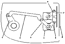
[0012] The implementation manner will be described below in conjunction with the accompanying drawings.

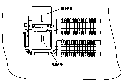
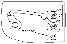
[0013] The rocker arm A is directly connected to the main shaft of one of the auxiliary switches, and the connecting plate A, the rocker arm A and the output link of the grounding switch form a set of transmission mechanism, so that the auxiliary switch can switch the opening and closing signals with the movement of the grounding switch; the two rocker arms B and rocker arm A belong to two different planes. Rocker arm B is directly connected to two auxiliary switches respectively. The connecting plate B and rocker B form a set of transmission mechanism. The two rocker arms B are arranged in parallel so that the two auxiliary switches can be separated simultaneously. Combined signal switching; the sign is connected to the connecting plate B, and reciprocates up and down with the connecting plate B; the observation window is made of transparent glass and fixed at a specific p...


PUM


Abstract

The invention relates to a transmission device capable of simultaneously achieving the purposes of remotely transmitting a grounding switch switch-on or switch-off signal and locally clearing a switch-on or switch-off state, and aims to provide a signal conversion transmission device which is high in space utilization rate, accurate in signal transmission, convenient for in-situ observation and easy to expand the capacity. The technical scheme is characterized in that (1) auxiliary switches, rocker arms, a connecting plate, an indication board and an observation window form a two-stage transmission mechanism, spindles of the two auxiliary switches are simultaneously driven to rotate under the rotation driving of a grounding switch connecting rod, and thus synchronous switched transmissionof signals of the two auxiliary switches is realized; (2) the indication board is connected with the transmission mechanism and moves up and down in a reciprocating manner along with the transmissionmechanism, and the synchronization between local indication and remote signal transmission is realized; (3) the observation window is set, information of an alignment area of the indication board andthe observation window is read, and the accessibility of a local switch-on or switch-off signal is realized; and (4) the transmission mechanism and the auxiliary switches are additionally arranged atcorresponding positions so as to realize capacity expansion of the auxiliary switches, and different use requirements are met.

Description

technical field [0001] The invention relates to a transmission device for switching and indicating the opening and closing signals of the grounding switch, in particular to a transmission device which adopts a mechanical transmission mechanism to simultaneously realize the remote transmission of the opening and closing signals of the grounding switch and clarify the opening and closing state of the grounding switch on the spot, and is easy to realize the expansion of the auxiliary switch transmission device. Background technique [0002] The grounding switch is an indispensable module in the combined electrical appliances of the power system. With the continuous development of the electrical equipment control system in recent years, the requirements for the number of auxiliary switch contacts of the grounding switch continue to increase, and it is necessary to equip the grounding switch with two or more auxiliary switches. The switch completes signal transmission and switchi...

Claims


Application Information

Patent Timeline
IPC IPC(8): H01H9/16H01H31/10
CPCH01H9/16H01H31/10
Inventor 高珍文亚宁沈鹏飞钟智攀刘波
Owner SHANGHAI SIEYUAN HIGH VOLTAGE SWITCHGEAR
Why Eureka
Try Eureka