
System for assembling electrical cabinets of an electrical switchboard

A technology for assembling systems and electrical cabinets, applied in the field of electrical cabinets, can solve the problems of no longer guaranteeing the performance of electrical cabinets, the solution is not completely satisfactory, reducing the use of nuts and bolts, etc., so as to reduce installation costs and reduce ground clearance. Surface, the effect of speeding up the assembly process

Active Publication Date: 2018-05-11
SCHNEIDER ELECTRIC IND SAS
View PDF6 Cites 0 Cited by
  • Summary
  • Abstract
  • Description
  • Claims
  • Application Information

AI Technical Summary

Problems solved by technology

[0004] Now, given the constraints of field installations, the scheme is not entirely satisfactory
In fact, it is often difficult to assemble the rear of the panel at the installation site, mainly because of inaccessibility, so that installers sometimes tend to reduce the use of nuts and bolts
As a result, the performance of the electrical cabinet is no longer guaranteed (especially in the case of internal arcing)

Method used


Image

  • System for assembling electrical cabinets of an electrical switchboard
  • System for assembling electrical cabinets of an electrical switchboard
  • System for assembling electrical cabinets of an electrical switchboard

Examples


Embodiment Construction

[0046] Throughout the description, it should be noted that the terms "front", "rear", "top", "bottom", "vertical" and "horizontal" are to be understood as considering the position of the electrical cabinet 2 of the switchboard 10 on the floor during installation. The usual positioning on .

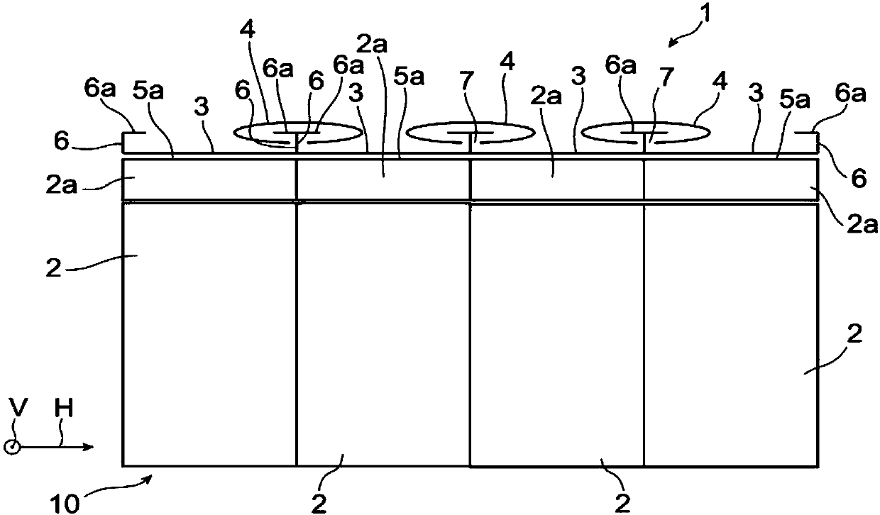
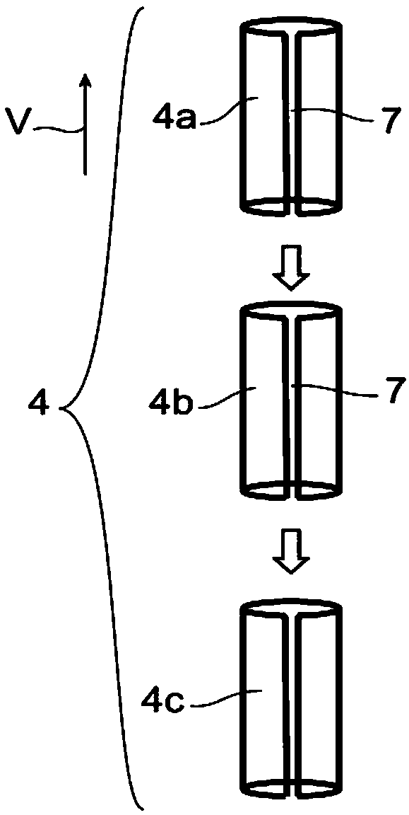
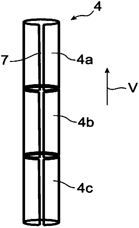
[0047] Also, it should be noted that in Figure 1-3 and 5-7A, the axis H represents the horizontal axis and the axis V represents the vertical axis.

[0048] refer to figure 1 , shows a switchboard 10 comprising four electrical cabinets 2 assembled by means of the assembly system 1 according to the invention.

[0049] According to the invention, the assembly system 1 comprises four metal rear fixing plates 3 . Each rear fixing plate 3 is fixed to the rear side 5 a of the rear portion 2 a of each electrical cabinet 2 .

[0050] Furthermore, each rear fixing plate 3 extends vertically along the rear side 5a of the corresponding electrical cabinet's rear portion 2a and has a substantially C...


PUM


Abstract

The invention discloses a system for assembling electrical cabinets of an electrical switchboard. The main object of the invention is an assembly system (1) of electrical cabinets (2) of an electricalpanel (10), characterized in that the system comprises: fixing rings (6) which vertically extend over the rear side (5a) of each electrical cabinet; one or a plurality of assembling rails (4) of which each assembling rail includes an inserting opening (7) which vertically extends, the assembling rail being designed to vertically slide over a group which is formed by engaging two fixing rings of two adjacent electrical cabinets, wherein the two fixing rings 6 are disposed inside the inserting opening.

Description

technical field [0001] The invention relates to the field of electrical cabinets for switchboards, and in particular to solutions for connecting such electrical cabinets to each other. [0002] The invention relates more particularly to electrical cabinets in the form of modular units with fixed or removable equipment insulated by air or gas inside a metal housing. Such a unit or cabinet can be used, for example, to form a high voltage section of an HV / LV distribution station as well as a high voltage transmission or distribution station. In this application, the term "high voltage" (HV) refers to voltages greater than 1000 volts. Background technique [0003] Traditionally, the assembly of electrical cabinets to each other in a switchboard is generally done by using nuts and bolts. [0004] Now, given the constraints of field installations, this solution is not entirely satisfactory. In fact, it is often difficult to assemble the rear of the panel at the installation sit...

Claims


Application Information

Patent Timeline
IPC IPC(8): H02B3/00
CPCH02B3/00H02B1/308H02B13/025
Inventor Y.马利尔B.维尔皮洛特
Owner SCHNEIDER ELECTRIC IND SAS
Learn More