Welding jig for evaporator core

A technology for welding fixtures and evaporator cores, which is applied in welding equipment, manufacturing tools, auxiliary devices, etc., can solve the problems of product quality, complex fixture structure, and high cost, and achieves improved welding process efficiency, simple assembly process, and simple structure. Effect

Active Publication Date: 2015-08-05
翰昂汽车零部件(北京)有限公司
View PDF6 Cites 0 Cited by
  • Summary
  • Abstract
  • Description
  • Claims
  • Application Information

AI Technical Summary

Problems solved by technology

Due to the complex structure of the fixture and the deformation after repeated high-temperature brazing, the size deviation of the positioning hole ⑥ leads to product quality problems
In addition, the self-weight of the fixture is 2.8kg, and the self-weight of the product is 1kg. Therefore, during the brazing process, the heat absorbed by the fixture (useless work) is higher than the heat absorbed by the product (useful work), resulting in energy waste; and the overseas procurement cycle is long, the cost is high, and the structure is complicated. , short life, low productivity in assembly and welding processes

Method used


Image

  • Welding jig for evaporator core
  • Welding jig for evaporator core
  • Welding jig for evaporator core

Examples


Embodiment Construction

[0013] The present invention proposes a welding jig for an evaporator core. Describe below in conjunction with accompanying drawing.

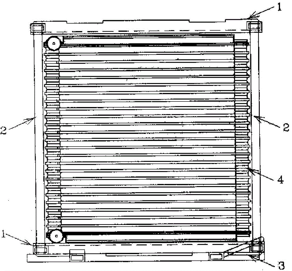
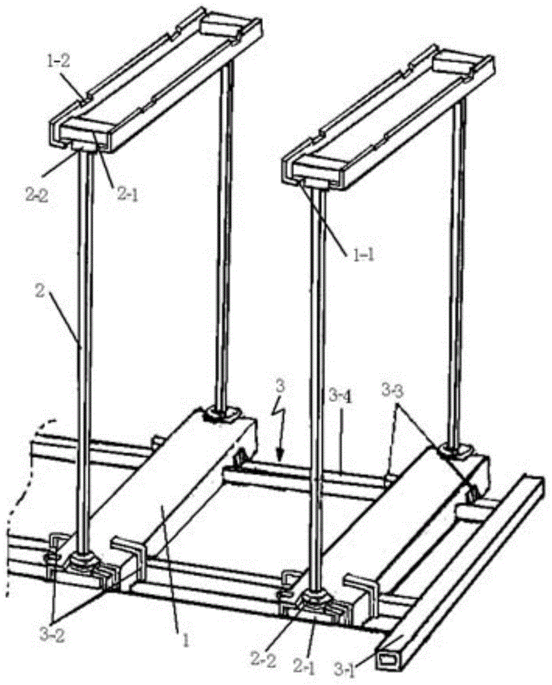
[0014] exist Figure 2-Figure 5 In the schematic diagram of the new welding fixture shown, the upper and lower cover plates 1 of the welding fixture have the same structure and are made of channel steel. A clamp square opening 1-1 is opened at both ends of the channel steel bottom, and a square opening 1-1 is opened on both sides. Two card slots 1-2 (such as Figure 4 Shown in a, b, c); Wherein the square opening 1-1 of the card bar is put into the connecting card bar 2, and the card slot 1-2 is stuck on the track 3-4 of the base 3, which plays the role of fixing the product. Both sides connecting clip 2 are fixed on connecting clip 2 two ends by upper and lower stopper 2-1 and upper and lower limit ring 2-2 (as Figure 5 As shown), the clips on both sides clamp the upper and lower cover plates and the product to form a whole, and the distan...


PUM


Abstract

The invention discloses a welding clamp for an evaporator core body, which belongs to the range of brazing auxiliary moulds. The welding clamp for the evaporator core body is formed by connecting an upper cover plate, a lower cover plate and two clamping strips on the two sides into a square frame, and fixing the clamping strips on the two sides to a base. A product is fixed in the frame and is placed in a welding furnace for welding. The welding clamp for the evaporator core body is simple in structure, low in cost, simple in assembly process and high in speed; the welding process efficiency is improved by 40 percent; and the service life of the clamp is prolonged to 3 to 5 years from 1 to 2 years.

Description

technical field [0001] The invention belongs to the scope of brazing auxiliary molds, in particular to a welding fixture used for the core of an evaporator. Background technique [0002] The welding fixtures of the existing automotive air-conditioning evaporator mainly play a role of supporting and fixing during the brazing process. Because it is a foreign technology cited, more than 95% of the tools and molds are imported from abroad. figure 1 Shown is the original imported fixture, which is composed of chassis base ①; rear support bar ②; side support frame ③; upper pressure plate ④; support plate ⑤ and cooling fins. When using, take out the upper pressing plate ④, put the product ⑧ into the fixture and then put the upper pressing plate ④ on the product, press the upper pressing plate ④ down a certain distance through the assembly equipment so that the sliding bayonets ⑦ at both ends of the upper pressing plate ④ are inserted into the The positioning holes ⑥ on both sides ...

Claims


Application Information

Patent Timeline
Patent Type & Authority Patents(China)
IPC IPC(8): B23K3/08
Inventor 时权尤爱杰
Owner 翰昂汽车零部件(北京)有限公司
Why Eureka
Try Eureka