
High sound pressure directional amplifying wave-guide horn

A technology of amplifying waves and horns, applied in the field of audio equipment, can solve the problems of poor, can only be oriented in one of the horizontal or vertical directions, the structure of the sound array horn and the driving circuit are complex, and the directivity control of ordinary horns is limited, etc., to achieve strong promotion. Meaning, the structure is simple and convenient, the effect of improving the sound pressure level

Pending Publication Date: 2018-05-11
东莞市三基音响科技有限公司
View PDF8 Cites 0 Cited by
  • Summary
  • Abstract
  • Description
  • Claims
  • Application Information

AI Technical Summary

Problems solved by technology

[0003] At present, the high sound pressure sound reinforcement speakers on the market usually use ordinary horns or sound array horns, but the directivity control of ordinary horns is limited, and it is not easy to combine or there are serious acoustic defects after combination
However, the structure and driving circuit of the sound array horn are relatively complicated, and the sound directivity of the sound array horn is poor, and it can only face one of the horizontal or vertical directions.

Method used


Image

  • High sound pressure directional amplifying wave-guide horn
  • High sound pressure directional amplifying wave-guide horn

Examples


Embodiment Construction

[0013] In order to make the purpose, technical solution and advantages of the invention clearer, the invention will be further described in detail below in conjunction with the accompanying drawings and embodiments. It should be understood that the specific embodiments described here are only used to explain the invention, not to limit the invention.

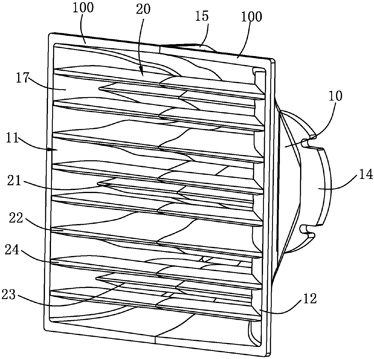
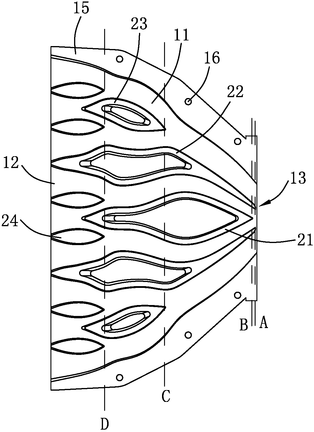
[0014] Such as figure 1 and figure 2 As shown, the present invention provides a high sound pressure directional sound amplification waveguide horn, and the high sound pressure directional sound amplification waveguide horn is composed of two symmetrical horn bodies 100 . The horn body 100 includes a main body 10 and a partition set 20 disposed in the main body 10. The two main parts 10 surround and form an inner cavity 11, and the two bulkhead sets 20 are connected to connect the inner cavity 11, etc. Divided into several sub-channels.

[0015] The main body 10 is arranged in a trumpet shape as a whole, and the rear end of t...


PUM


Abstract

The invention provides a high sound pressure directional amplifying wave-guide horn, composed of two symmetric horn bodies. The horn body comprises a main body part and a partition board group arranged in the main body part; the two main body parts are enclosed to form an inner cavity; and the two partition board groups are connected to divide the inner cavity into a number of sub-channels; the total length of the number of sub-channels from throat to sound outlet is the same, and the width of each sub-channel at the location with the same length is the same. Therefore, the horn has wide horizontal directivity and narrow vertical directivity which can be controlled; meanwhile, the sound pressure and the sound energy can be evenly distributed in the coverage area and the necessary height effectively, therefore, the sound energy utilization efficiency is improved, and the sound directivity is optimized; in addition, the high sound pressure directional amplifying wave-guide horn providedby the invention is small in size and easy to carry, and the structure is simple, which is easy to form array horns to further increase the amplifying sound pressure; the practicality is good; and thehigh sound pressure directional amplifying wave-guide horn has a good popularization significance.

Description

technical field [0001] The invention relates to the field of audio equipment, in particular to a high-sound-pressure directional sound-expanding waveguide horn. Background technique [0002] The horn refers to a channel of a specific shape installed in front of the horn, which can compress and amplify sound waves, and can also constrain and change the direction of propagation. The length of the horn and the size of the opening affect the cut-off point of the lowest frequency that the horn can produce, which is closely related to the acoustic characteristics of the horn. The shape of most loudspeaker horns is a conventional horn shape that evenly transitions from a small space to a large space. It plays a directional transmission of sound, changes the frequency, and changes the sound pressure of a specific frequency. [0003] At present, the high sound pressure sound reinforcement speakers on the market usually use ordinary horns or sound array horns, but the directivity con...

Claims


Application Information

Patent Timeline
Patent Type & Authority Applications(China)
IPC IPC(8): H04R1/28
CPCH04R1/28
Inventor 杨军姜振华闻克俭
Owner 东莞市三基音响科技有限公司
Learn More