Automatic gain control circuit based on photoresistor

A technology of automatic gain control and photoresistor, which is applied in the electrical field, can solve problems such as complex circuits, non-continuously adjustable circuit gain, and inaccurate control of the output voltage amplitude, and achieve simple circuit structure, easy-to-understand principles, and easy-to-understand circuit parameters The effect of adjustment

Inactive Publication Date: 2016-11-23
SOUTH CHINA UNIV OF TECH
View PDF8 Cites 6 Cited by
  • Summary
  • Abstract
  • Description
  • Claims
  • Application Information

AI Technical Summary

Problems solved by technology

There are many ways to realize the controllable gain amplifier, such as using an analog electronic switch, a resistor network and an operational amplifier to form an amplifying circuit, and selecting a resistor through an analog switch to change the gain of the amplifier, but such a circuit gain is not continuously adjustable, resulting in the final The output voltage amplitude cannot be precisely controlled; another example is a differential circuit made of transistors or mos tubes, but such a circuit is more complicated, and it is difficult to know the actual magnification of the circuit

Method used


Image

  • Automatic gain control circuit based on photoresistor
  • Automatic gain control circuit based on photoresistor
  • Automatic gain control circuit based on photoresistor

Examples


Embodiment

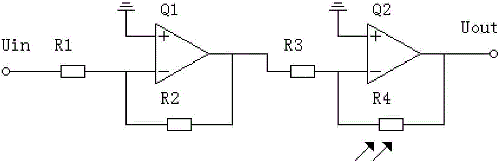
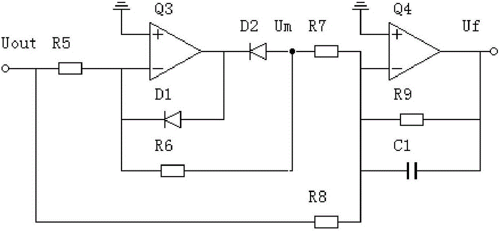
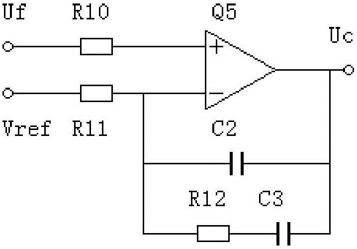
[0023] Such as Figure 5 As shown, an automatic gain control circuit based on a photoresistor includes a controllable gain amplifier, a rectification filter circuit, an op amp PI regulator and a photodiode drive circuit. The input signal is passed through a controllable gain amplifier to obtain an output signal, and the output signal The control signal is obtained through the rectification filter circuit and the operational amplifier PI regulator, and then the gain of the controllable gain amplifier is adjusted through the photodiode drive circuit to form a negative feedback loop;

[0024] The controllable gain amplifier is composed of an inverting follower and an inverting amplifier, the inverting follower is composed of an operational amplifier Q1, a resistor R1 and a resistor R2, and the inverting amplifier is composed of a resistor R4 as a feedback resistor and an operational amplifier Q2 and resistor R3, the resistor R4 is a photosensitive resistor, and the output signal ...


PUM


Abstract

The invention discloses an automatic gain control circuit based on a photoresistor. The circuit comprises a controllable gain amplifier, a rectification filtering circuit, an operational amplifier PI regulator and a photodiode drive circuit. An input signal passes through the controllable gain amplifier, thereby obtaining an output signal. The output signal passes through the rectification filtering circuit and the operational amplifier PI regulator, thereby obtaining a control signal. The gain of the controllable gain amplifier is adjusted through the photodiode drive circuit, thereby forming a negative feedback circuit. The controllable gain amplifier is composed of an inverted voltage follower and an inverted amplifier. A resistor R4 is taken as a feedback resistor of the inverted amplifier. The resistor R4 is a photoresistor. According to the circuit, the controllable gain amplifier is composed of the photoresistor, the gain is continuously adjustable, and the amplitude of the output signal can be controlled precisely.

Description

technical field [0001] The invention relates to the field of electrical technology, in particular to an automatic gain control circuit based on a photosensitive resistor. Background technique [0002] In wireless communication, due to the influence of various external factors, such as different signal transmission power, attenuation in the signal propagation process and the influence of noise, the strength of the signal received by the receiver varies, often with a large gap. For these signals of different strengths, the receiver needs to use an automatic gain control circuit. The purpose is to adjust its own amplification factor according to the strength of the input signal, so that a signal with an appropriate amplitude is always output and provided to the receiver for next-level processing. , to ensure the stable operation of the receiver. [0003] The implementation of automatic gain control circuit can be divided into software implementation and hardware implementation...

Claims


Application Information

Patent Timeline
Patent Type & Authority Applications(China)
IPC IPC(8): H03G3/30
CPCH03G3/3084
Inventor 王孝洪叶健豪潘志锋田联房陈英杰黄氏秋江
Owner SOUTH CHINA UNIV OF TECH
Why Eureka
Try Eureka