Supercharge Your Innovation With Domain-Expert AI Agents!

Chemical conversion system to replace empty containers with full ones

A container and destination technology, applied in the direction of machines/engines, liquid variable displacement machines, liquid flow control devices, etc., can solve problems such as troublesome conversion process and difficulties, and achieve the effect of reducing impact

Active Publication Date: 2020-06-16
SEALED AIR SAS
View PDF25 Cites 0 Cited by
  • Summary
  • Abstract
  • Description
  • Claims
  • Application Information

AI Technical Summary

Problems solved by technology

[0009] However, the arrangement of submersing the pump in the supply container may require a difficult and possibly cumbersome changeover process to withdraw the pump from an empty supply container and install it in a full supply container

Method used


Image

  • Chemical conversion system to replace empty containers with full ones
  • Chemical conversion system to replace empty containers with full ones
  • Chemical conversion system to replace empty containers with full ones

Examples


Embodiment Construction

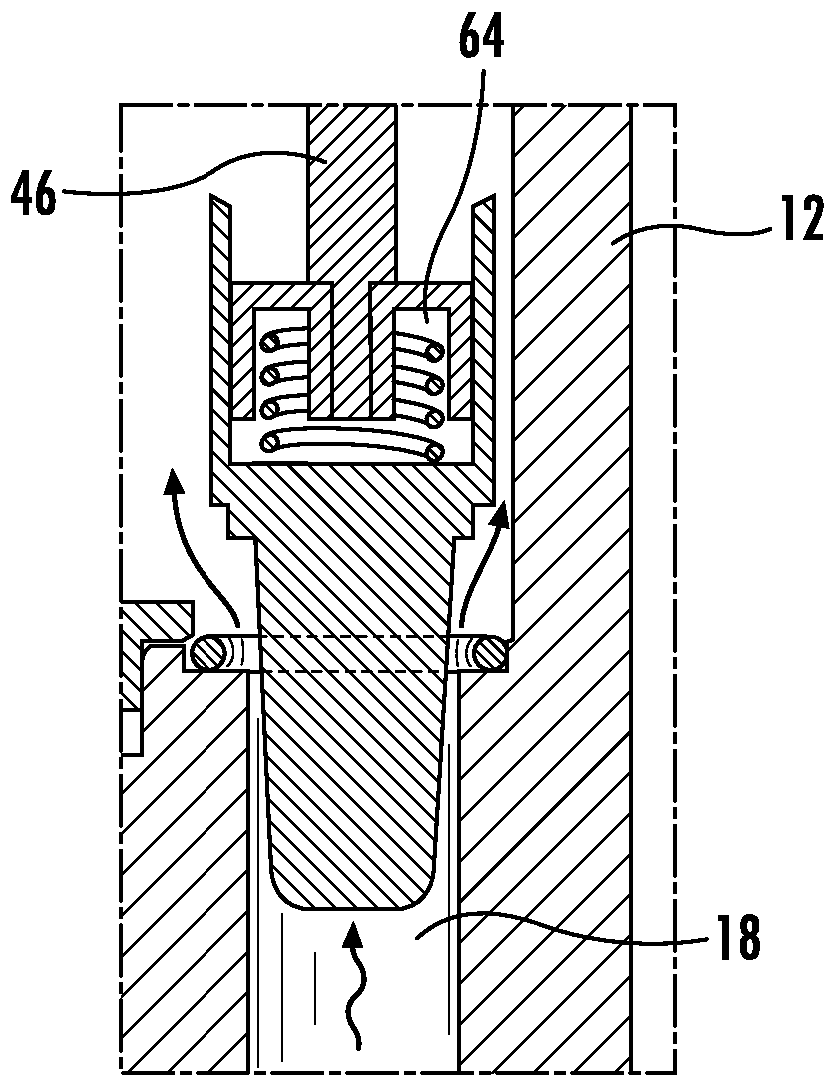
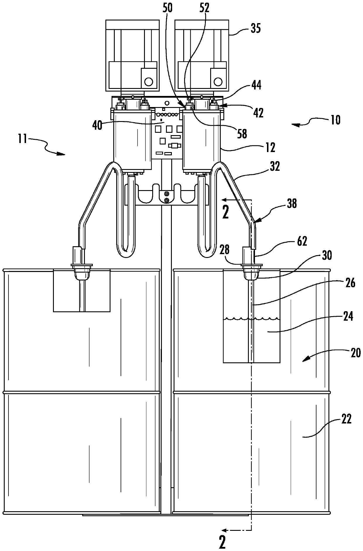
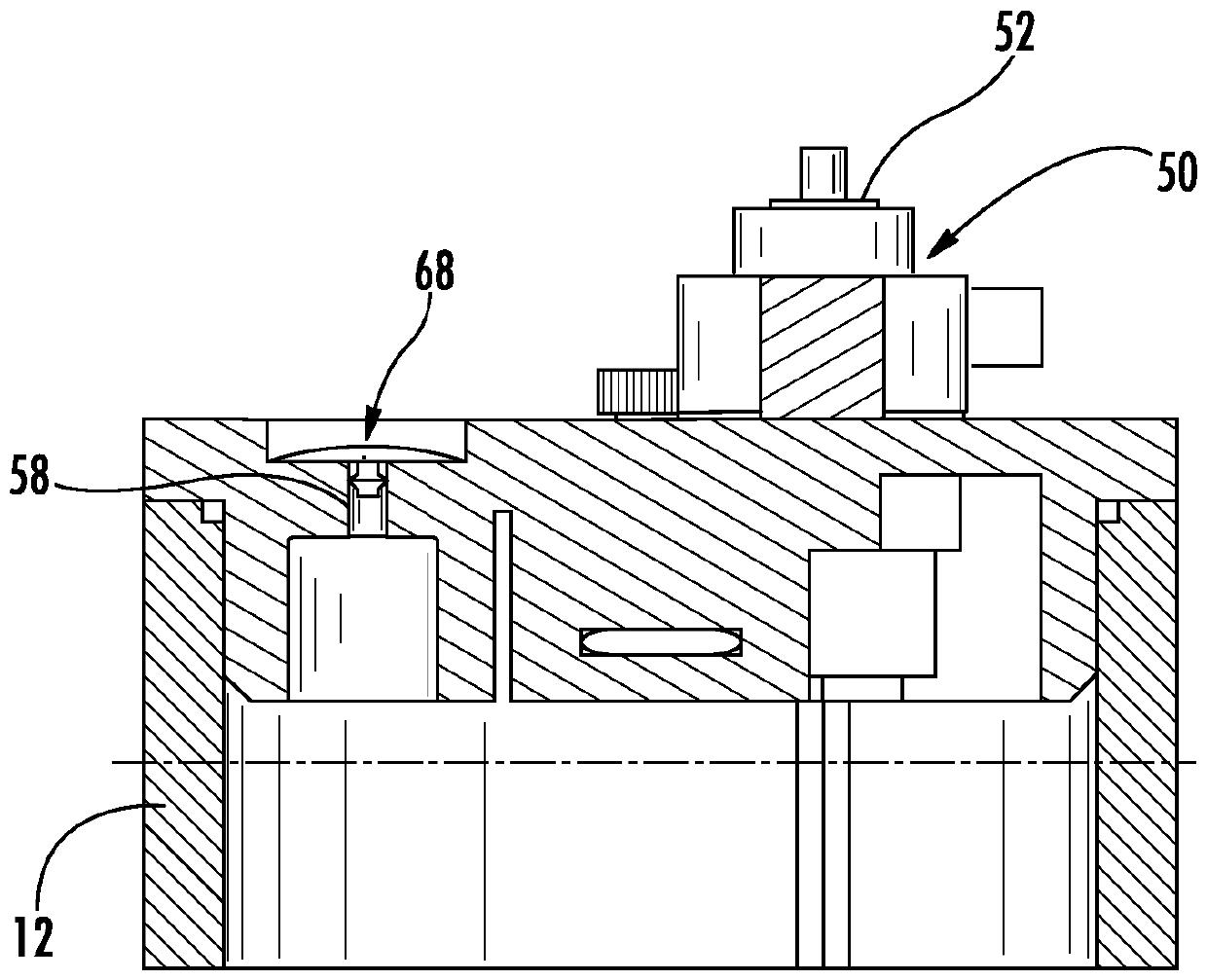
[0030] Embodiments of the disclosed subject matter relate to a system 10 ( figure 1 , 7 ), which has a storage tank 12, a pump 14 within the storage tank, a discharge path 16 connecting the pump outlet 66 to the storage tank 12, and a recirculation path 18 connecting the pump inlet 34 to the storage tank 12, as herein as described in more detail.

[0031] The system 10 operates to supply liquid from a liquid source 20 to a destination outside of the storage tank 12, such as, for example, to a dispensing valve 100 ( Figure 14 ), or to a dispenser for foam-in-bag or foam-in-place equipment (used to mix liquids to create polyurethane foam). The destination receives liquid 24 from pump outlet 66 . ( figure 1 , 7 ). although figure 1 Two supply systems are shown (ie, system 10 and system 11 ), but only system 10 is described in detail herein because system 11 is generally similar to system 10 . System 10 and system 11 may cooperate to provide two different liquids to th...


PUM


Abstract

A system for supplying a liquid. A reservoir tank has a low level and a high level of the liquid. A pump is submerged in the liquid within the reservoir tank. The pump has an inlet to receive the liquid from a source outside of the reservoir tank and an outlet to deliver the liquid to a destination outside of the reservoir tank. A bleed path places the pump outlet in fluid communication with the reservoir tank. The bleed path has a bleed valve controlling the flow of liquid through the bleed path to maintain the liquid level in the reservoir tank above the low level. A recirculation path places the pump inlet in fluid communication with the reservoir tank. The recirculation path has a recirculation valve controlling the flow of liquid through the recirculation path to maintain the liquid level in the reservoir tank below the high level.

Description

[0001] cross reference [0002] This application claims the benefit of US Provisional Application No. 62 / 167530, filed May 28, 2015, which is hereby incorporated by reference in its entirety. technical field [0003] Various embodiments of the disclosed subject matter relate to systems for supplying liquids, such as isocyanate liquids, from containers to end-use locations. Background technique [0004] The foamable composite is typically formed by mixing an isocyanate compound with a hydroxyl-containing material such as a polyol (ie, a compound containing multiple hydroxyl groups) in the presence of water and a catalyst. Isocyanates and polyol precursors react to form polyurethanes. At the same time, the water reacts with the isocyanate compound to produce carbon dioxide. The carbon dioxide expands the polyurethane into a foam cellular structure (ie, polyurethane foam), which can be used to protect or cushion the packaged object. [0005] In "foam-in-bag" packaging, a ma...

Claims


Application Information

Patent Timeline
Patent Type & Authority Patents(China)
IPC IPC(8): F04B23/02B29C44/00B29C44/36F04F10/00
CPCB29C44/182B29K2075/00B29K2105/04F04B23/021F04F10/00B67D7/68B67D7/78B67D2210/00
Inventor M.H.萨勒诺
Owner SEALED AIR SAS
Features
  • R&D
  • Intellectual Property
  • Life Sciences
  • Materials
  • Tech Scout
  • Unparalleled Data Quality
  • Higher Quality Content
  • 60% Fewer Hallucinations
Learn More