Tank with fill level indicator and compact unit with such a tank

An indicator, level sensor technology for use in the field of compact units

Active Publication Date: 2020-12-08
ROBERT BOSCH GMBH
View PDF6 Cites 0 Cited by
  • Summary
  • Abstract
  • Description
  • Claims
  • Application Information

AI Technical Summary

Problems solved by technology

[0005] The disadvantage of such a visual fill level indicator is that the sight glass always has to be viewed approximately vertically in order to be able to detect the level of hydraulic oil in the interior space of the tank

Method used


Image

  • Tank with fill level indicator and compact unit with such a tank
  • Tank with fill level indicator and compact unit with such a tank
  • Tank with fill level indicator and compact unit with such a tank

Examples


Embodiment Construction

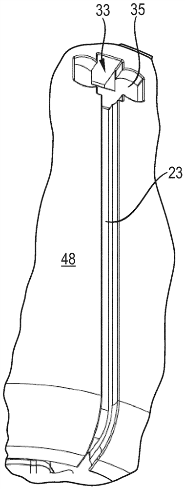
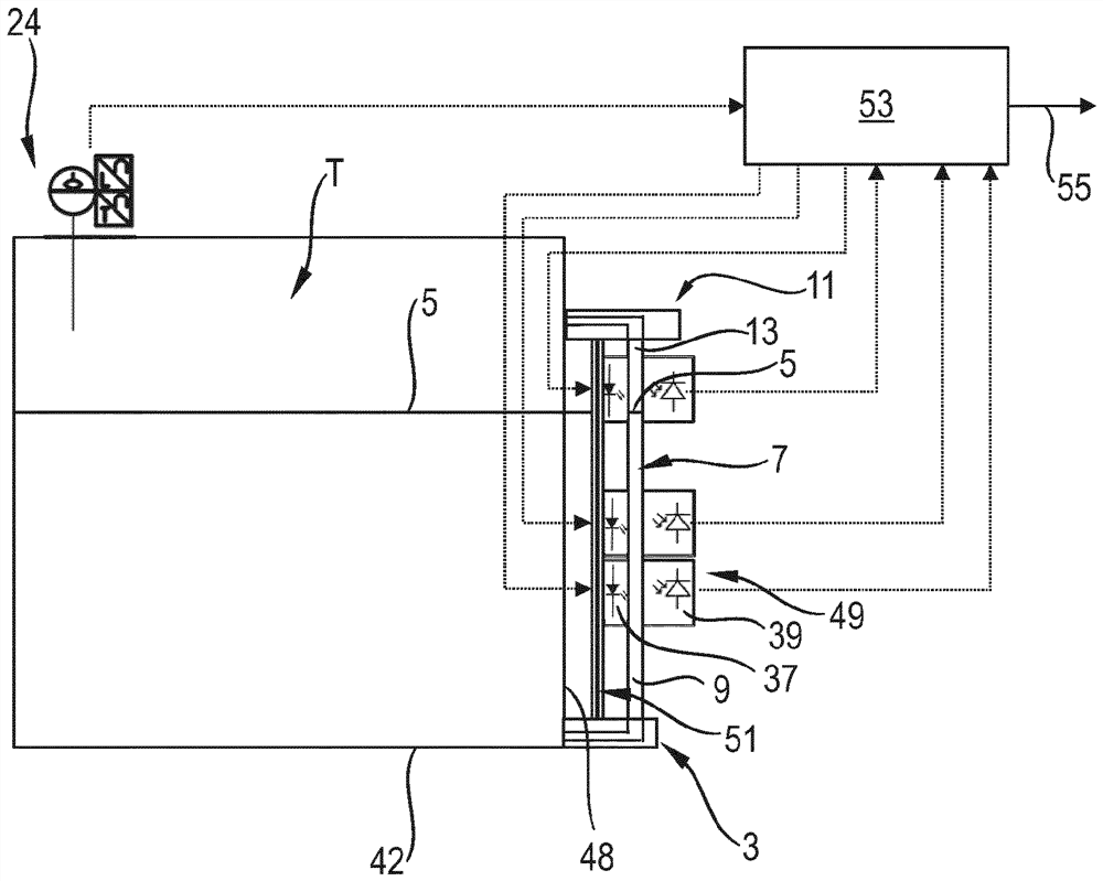
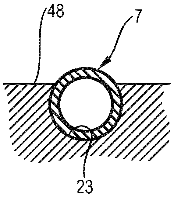
[0038] figure 1 A first exemplary embodiment of a tank T is shown in a schematic side view, in the interior of which hydraulic oil is accommodated with a fill level 5 . In the lower region of the outer wall 48 , the lower connection 3 is arranged as close as possible to the bottom 42 of the tank T. As shown in FIG. This lower connection connects the hose 7—more precisely its first end section 9—to the interior of the tank T via a bent channel. The hose 7 runs vertically and parallel to the outer wall 48 . exist figure 1 In the indicated position shown, the hose 7 has the function of a riser. The hose 7 thus serves as a visual fill level indicator which can be read from a wide angular range of approximately 180° from the outside of the tank T.

[0039]Above the filling level 5 , the upper connection 11 is arranged on the outer wall 48 of the tank T. As shown in FIG. In the indicated position of the hose 7 , the second end section 13 of the hose 7 is also connected to the u...


PUM


Abstract

A tank is disclosed which has a hose extending on its side wall which serves as a fill level indicator and can also be used here as a discharge hose. In its function as a fill level indicator, the hose or its upper end section is fixed in the holder in such a way that it is oriented approximately upwards. During its function as a discharge hose, the hose or its upper end section is released from the holder and bent downwards.

Description

technical field [0001] The invention relates to a tank with a visual fill level indicator according to the preamble of patent claim 1 and to a compact unit with such a tank. Background technique [0002] In tanks, for example, which receive hydraulic oil, sight glasses are known as visual fill level indicators which are inserted into the outer wall of the tank. [0003] The compact unit has a tank from which pressure medium can be fed to the load connection via the drive unit. [0004] In the applicant's publication number RE 51013 version 11.14, data sheet "Modularstandard power units Type ABSKG" discloses an electrohydraulic unit with a tank in which such a Sight glass. [0005] A disadvantage of such a visual fill level indicator is that the sight glass always has to be viewed approximately vertically in order to be able to detect the hydraulic oil level in the interior of the tank. Contents of the invention [0006] In contrast, the object of the present invention i...

Claims


Application Information

Patent Timeline
Patent Type & Authority Patents(China)
IPC IPC(8): F17C1/00F17C13/02
CPCF15B1/26F15B2211/6303F17C1/00F17C13/021F17C2205/05F17C2250/0413F17C2250/0417
Inventor A.京德
Owner ROBERT BOSCH GMBH
Why Eureka
Try Eureka