Dynamic transaction card power management

A transaction card, dynamic technology, used in instruments, secondary battery repair/maintenance, electrochemical generators, etc., can solve complex smart card power management topology and other issues

Inactive Publication Date: 2018-05-11
CAPITAL ONE SERVICES
View PDF6 Cites 2 Cited by
  • Summary
  • Abstract
  • Description
  • Claims
  • Application Information

AI Technical Summary

Problems solved by technology

This current design also requires the use of complex smart card power management topologies

Method used


Image

  • Dynamic transaction card power management
  • Dynamic transaction card power management
  • Dynamic transaction card power management

Examples


Embodiment Construction

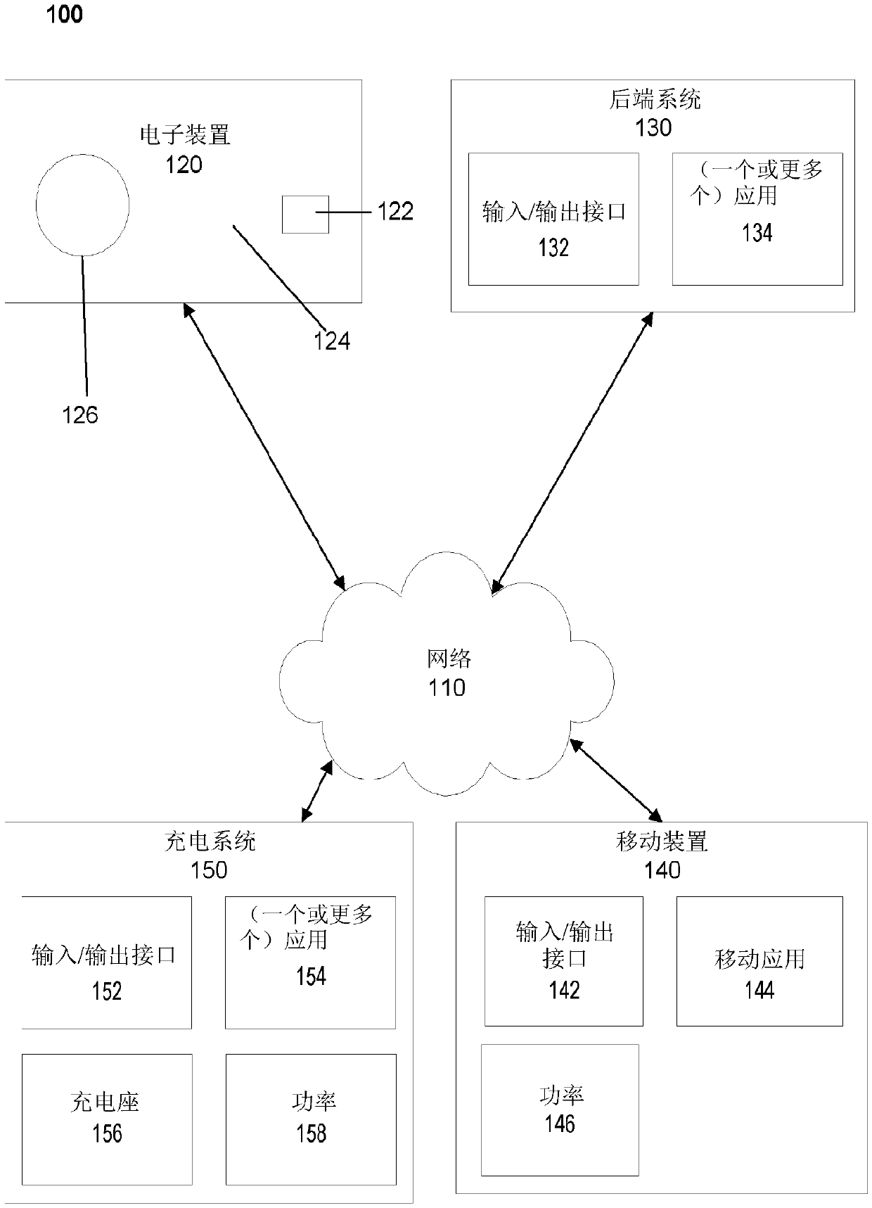
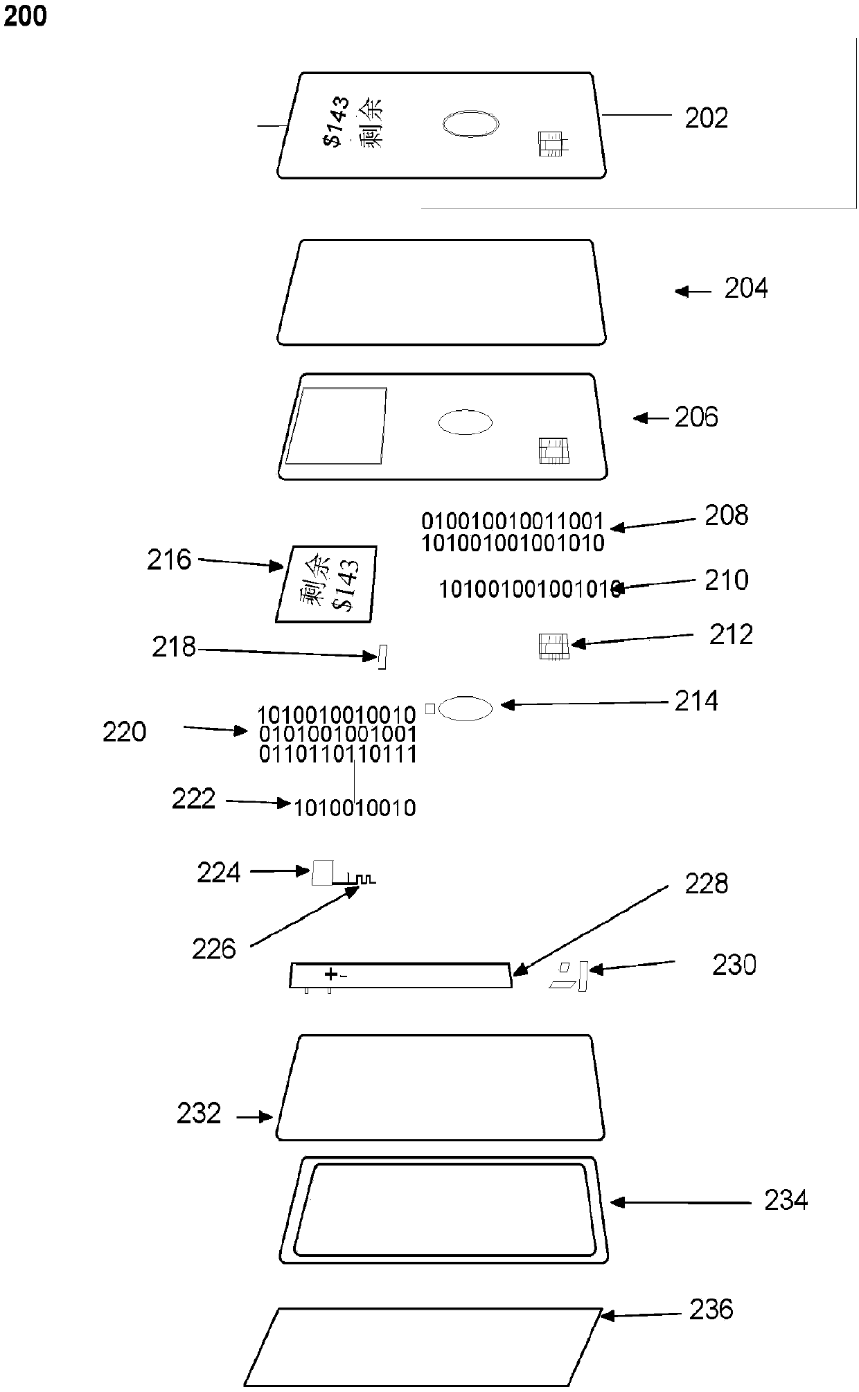
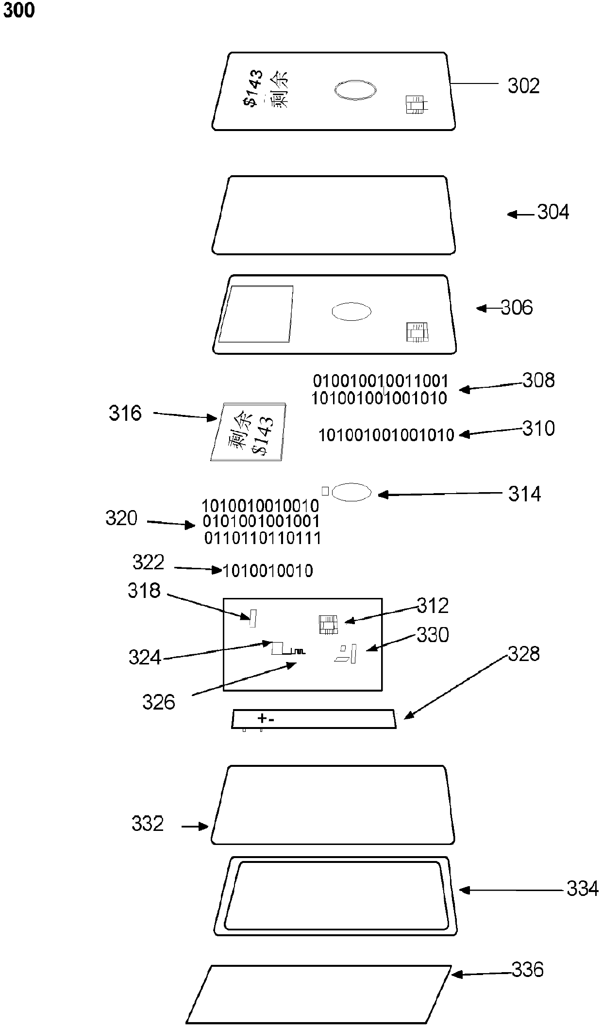
[0038] The following description is intended to express a thorough understanding of the embodiments described by providing several specific example embodiments and details related to a PCB with a power supply and a method for manufacturing a PCB with a power supply so that The dynamic transaction card can draw the power it needs to communicate with the smartphone by being inserted into the EMV terminal for payment. The associated system can collect energy from the EMV terminal to charge or recharge the dynamic transaction card when the card is inserted into the terminal. However, it should be understood that the present disclosure is not limited to these specific embodiments and details, which are only examples. It should also be understood that, given the known systems and methods, those of ordinary skill in the art will understand that the present invention is used for its intended purpose and benefits in any number of alternative embodiments depending on the specific design ...


PUM


Abstract

A printed circuit board ("PCB") with a power source. The PCB and power source combination may be inserted into a small electronic device, such as a dynamic transaction card, which may include a dynamic transaction card or a EuroPay-MasterCard-Visa ("EMV") card. For example, a PCB may be manufactured to attach a battery as a power source to one side of a PCB such that the integrated battery directly connects with at least a portion of the PCB side. A rapid energy storage device may also be utilized as a power source. Energy may be harvested from an EMV terminal to charge or recharge a dynamic transaction card or EMV card powered by a rapid energy storage device when the card is inserted into the terminal.

Description

[0001] Cross references to related applications [0002] This application requests U.S. Provisional Application No. 62 / 266,324, filed on December 11, 2015, titled "Printed Circuit Board with Integrated Battery", and the title filed on December 21, 2015 is " Capacitive Powertrain for a Smart Card" U.S. Provisional Application No. 62 / 270,307 and filed on March 9, 2016 entitled "Smart Card Europay MasterCard Visa ('EMV') Terminal Energy Collection ( Smart Card Europay MasterCard Visa ('EMV') Terminal Energy Harvesting)" U.S. Provisional Application No. 62 / 305,599 and filed on April 14, 2015 entitled "Systems, methods and equipment for dynamic transaction cards (System, Method, and Apparatus for a Dynamic Transaction Card)" U.S. Provisional Application No. 62 / 147,568. The entire contents of these applications are incorporated herein by reference. [0003] This application relates to the U.S. Application No. 14 / 338,423 filed on July 23, 2014, entitled "System and Method for Exchanging ...

Claims


Application Information

Patent Timeline
Patent Type & Authority Applications(China)
IPC IPC(8): G06K19/067G06K19/077
CPCG06K19/0702G06K19/0703G06K19/0704G06K19/0707H01M10/425H01M10/44H01M10/46H01M16/00G06K19/0701H02J7/00Y02E60/10G06K19/07707H02J7/345
Inventor T·洛克D·乌姆菲尔德J·扎拉卡斯A·R·柯培尔
Owner CAPITAL ONE SERVICES
Why Eureka
Try Eureka