A clamping device for riveting assembly of large thin-walled components

A component and thin-walled technology, applied in the field of fixtures, can solve the problems of inaccurate positioning and low quality consistency of large thin-walled parts, and achieve the effects of improving assembly quality, assembly processing efficiency, and reliability

Active Publication Date: 2019-11-12
BEIJING POWER MACHINERY INST
View PDF5 Cites 0 Cited by
  • Summary
  • Abstract
  • Description
  • Claims
  • Application Information

AI Technical Summary

Problems solved by technology

[0004] The invention provides a clamping device for riveting assembly of large thin-walled components, which can solve the problems of inaccurate positioning and low quality consistency during assembly of large thin-walled components

Method used


Image

  • A clamping device for riveting assembly of large thin-walled components
  • A clamping device for riveting assembly of large thin-walled components
  • A clamping device for riveting assembly of large thin-walled components

Examples


Embodiment Construction

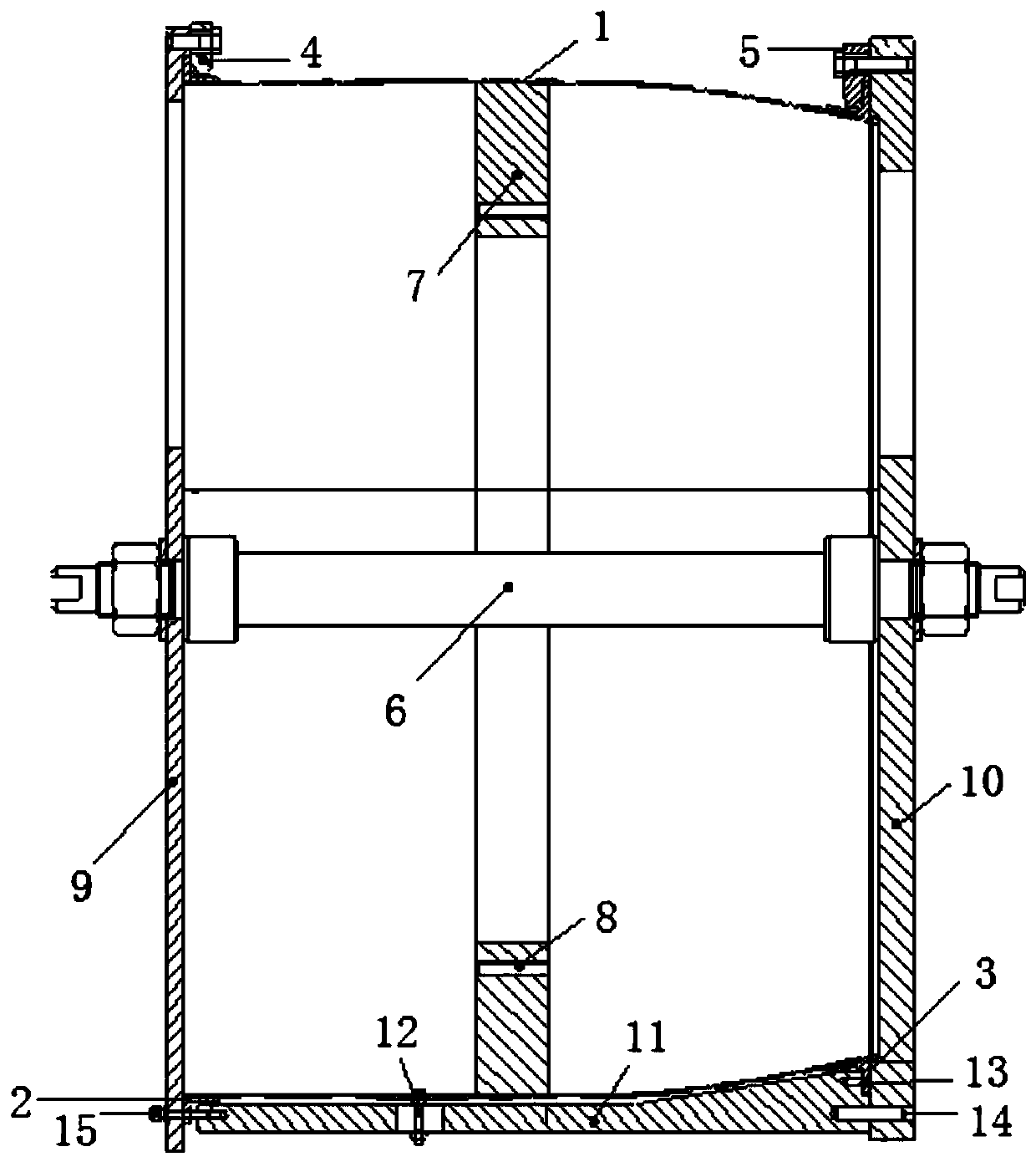
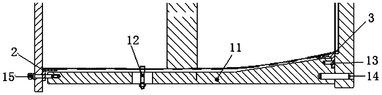
[0018] Such as figure 1 As shown, the present invention provides a clamping device for riveting and assembling large-scale thin-walled components. Pressing plate 4 and right pressing plate 5; the peripheral equipment is cylinder body 1 to be assembled and processed, left flange 2 and right flange 3;

[0019] Wherein, two right-angle steps are processed on the mandrel 6;

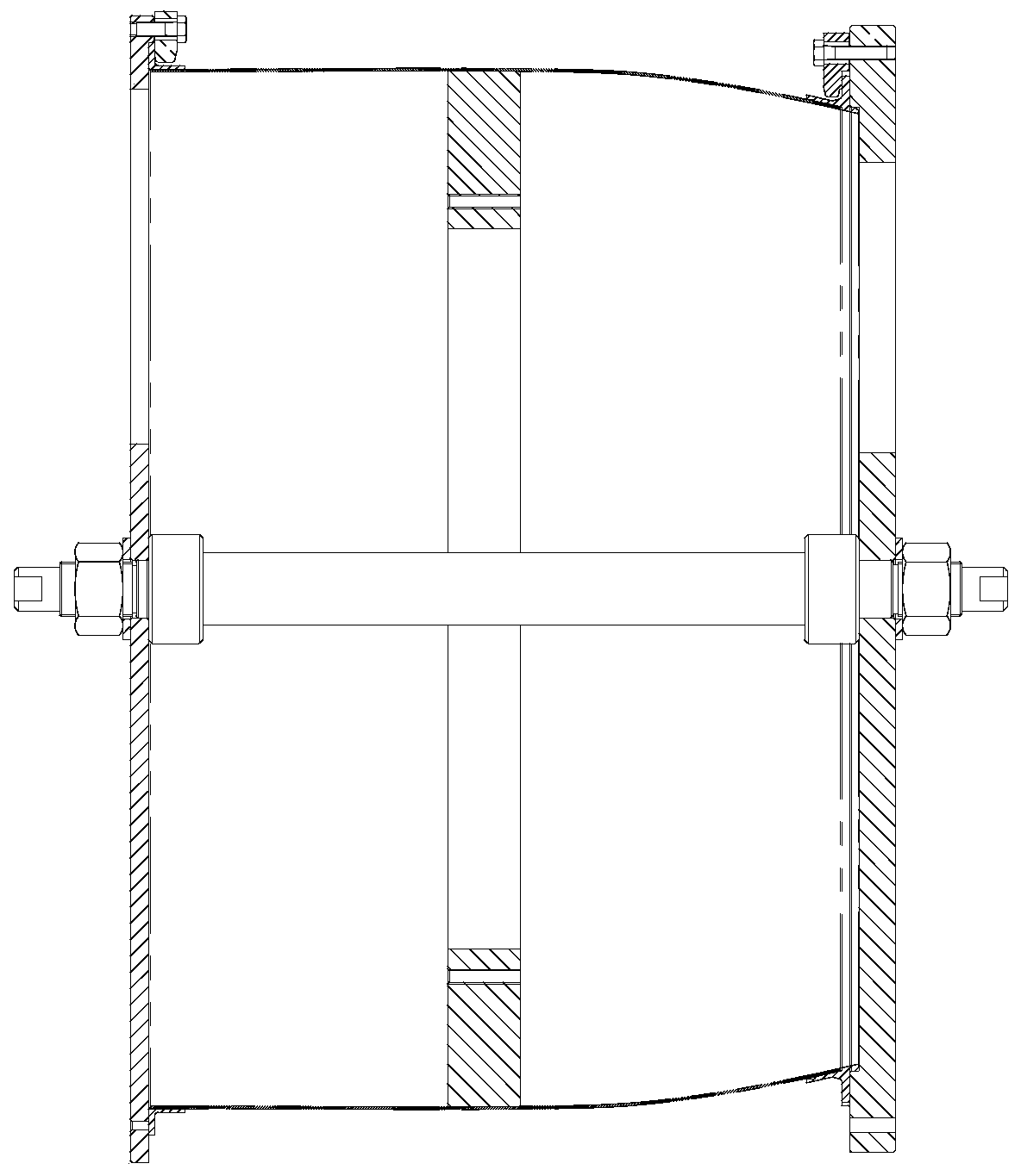
[0020] as attached Figure 4 As shown, the left blocking disk 9 and the right blocking disk 10 are annular plate-shaped structures, the middle part is a cross-shaped frame, and the center is processed with a central hole for the mandrel 6 to pass through;

[0021] The left flange 2 is connected to the left blocking plate 9 through the left pressing plate 4, and the right flange 3 is connected to the right blocking plate 10 through the right pressing plate 5. The end faces are fitted, and the two ends of the mandrel 6 pass through the center holes of the left blocking plate 9 and the right blocking plate 10...


PUM


Abstract

The invention discloses a clamping device for riveting assembling of a large thin-walled assembly. The clamping device comprises a mandrel shaft, an angular positioning assembly, a left plugging disc,a right plugging disc, a left pressing plate and a right pressing plate. Peripheral equipment is a to-be-clamped barrel, a left flange and a right flange. The left flange is connected to the left plugging disc through the left pressing plate. The right flange is connected to the right plugging disc through the right pressing plate. The inner side faces of the left plugging disc and the right plugging disc are attached to the two end faces of the barrel. The mandrel shaft penetrates through center holes of the left flange and the right flange to fix the barrel, the left flange and the right flange together. The angular positioning assembly achieves angular positioning between the left flange, the right flange and the barrel by being matched with pin holes in the left flange, the right flange and the barrel. After the angular positioning assembly is disassembled, machining of each rivet hole of an outer ring of the assembly and the mounting seat position is completed, and the double functions of assembling positioning and mechanical machining clamping are achieved. The clamping device can solve the problems that positioning during assembling of the large thin-walled part is not accurate, and the quality uniformity is not high.

Description

technical field [0001] The invention relates to a clamping device for riveting assembly of large thin-walled components, belonging to the technical field of fixtures. Background technique [0002] The core parts of the turbofan engine, the casing in the outer culvert and the casing in the outer culvert, are large thin-walled components, with a maximum diameter of more than 600mm. The main structure, that is, the cylinder, is made of aluminum alloy sheet metal, and its shape is a thin-walled cylindrical cylinder. Body, the flange structure of the aluminum alloy machined parts riveted at both ends, since the outer wall of the cylinder and the flange are attached with various mounting seats, the relative position of each mounting seat and the height of the casing are the key dimensions. [0003] The outer diameter of the casing parts is large, the wall of the sheet metal parts is thin, and the rigidity is not good. The conventional inner support components are easy to slide and...

Claims


Application Information

Patent Timeline
Patent Type & Authority Patents(China)
IPC IPC(8): B21J15/42
CPCB21J15/42
Inventor 赵颖颖周贺苏云玲李垒栋吕静麻丽红
Owner BEIJING POWER MACHINERY INST
Why Eureka
Try Eureka