High-safety floor drilling machine for assembling building water pipes

A high-safety, installation-use technology, applied in the field of punching machines, can solve the problems of people being injured, debris falling, time-consuming and labor-intensive, etc.

Inactive Publication Date: 2018-05-15
冯云鹏
View PDF4 Cites 8 Cited by
  • Summary
  • Abstract
  • Description
  • Claims
  • Application Information

AI Technical Summary

Problems solved by technology

[0005] In order to overcome the time-consuming and labor-intensive time-consuming and labor-intensive drilling of the floor, the present invention is easy to cause a large amount of debris to fall when drilling, thus affecting the surrounding environment. The technical problem to be solved is to provide a time-saving and labor-saving method that can collect and dispose of falling debris without affecting the surrounding environment, and the debris is not easy to smash people's doors, and can also cool the drill bit with high safety. Floor punching machine for building water pipe installation

Method used


Image

  • High-safety floor drilling machine for assembling building water pipes
  • High-safety floor drilling machine for assembling building water pipes
  • High-safety floor drilling machine for assembling building water pipes

Examples


Embodiment 1

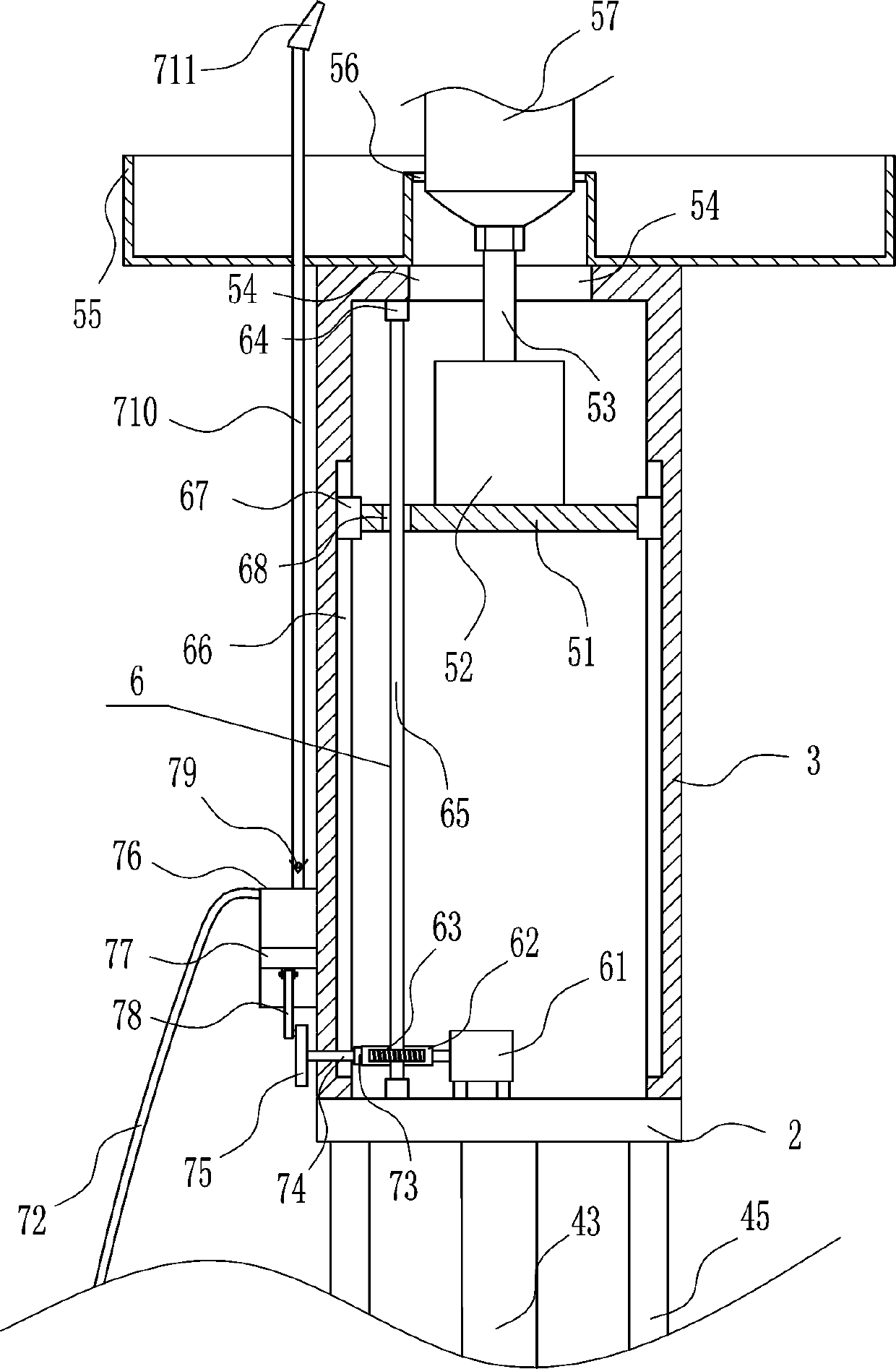
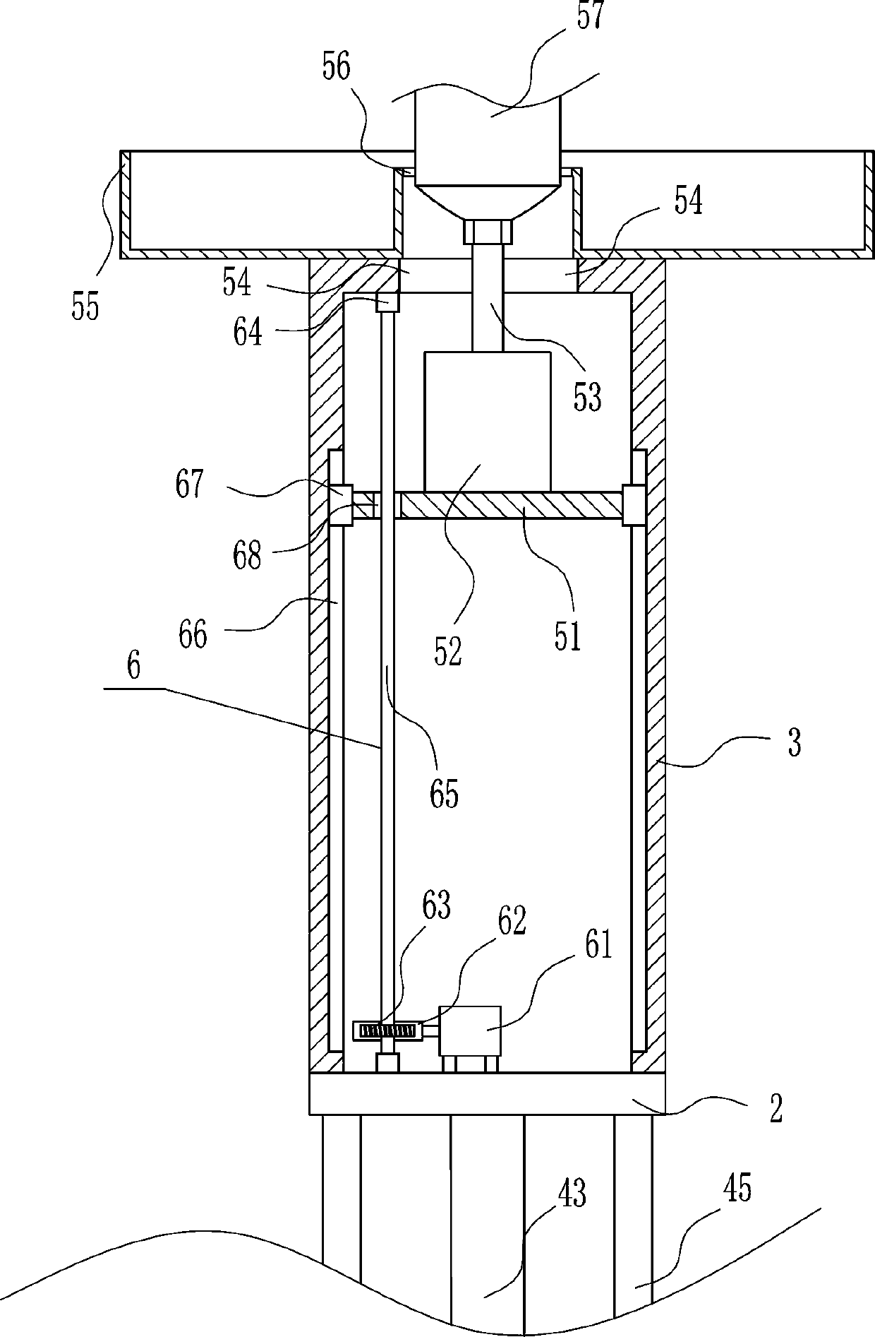
[0036] A floor punching machine for high security building water pipe installation, such as Figure 1-6 As shown, it includes a bottom plate 1, a horizontal plate 2, a frame body 3, a lifting device 4 and a punching device 5, a lifting device 4 is arranged in the middle of the top of the bottom plate 1, and a horizontal plate 2 is connected to the lifting part of the lifting device 4, and the horizontal plate 2 A frame body 3 is installed on the top, and a punching device 5 is arranged inside the frame body 3, and the punching parts of the punching device 5 are located outside the frame body 3.

Embodiment 2

[0038] A floor punching machine for high security building water pipe installation, such as Figure 1-6 As shown, it includes a bottom plate 1, a horizontal plate 2, a frame body 3, a lifting device 4 and a punching device 5, a lifting device 4 is arranged in the middle of the top of the bottom plate 1, and a horizontal plate 2 is connected to the lifting part of the lifting device 4, and the horizontal plate 2 A frame body 3 is installed on the top, and a punching device 5 is arranged inside the frame body 3, and the punching parts of the punching device 5 are located outside the frame body 3.

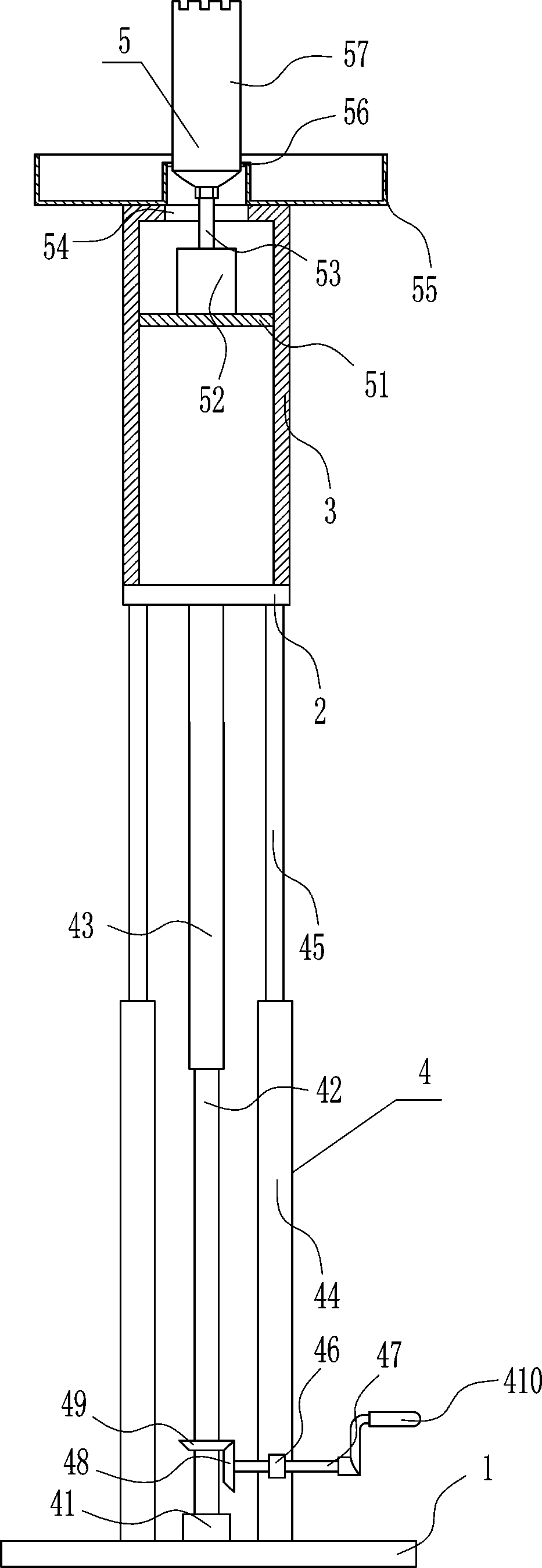
[0039] The lifting device 4 includes a first bearing seat 41, a screw rod 42, a first sleeve 43, a second sleeve 44, a lifting rod 45, a second bearing seat 46, a first rotating rod 47, a first bevel gear 48, a second The bevel gear 49 and the rotating handle 410, the top left and right sides of the bottom plate 1 are symmetrically equipped with a second sleeve 44, the second sleeve 4...

Embodiment 3

[0041] A floor punching machine for high security building water pipe installation, such as Figure 1-6 As shown, it includes a bottom plate 1, a horizontal plate 2, a frame body 3, a lifting device 4 and a punching device 5, a lifting device 4 is arranged in the middle of the top of the bottom plate 1, and a horizontal plate 2 is connected to the lifting part of the lifting device 4, and the horizontal plate 2 A frame body 3 is installed on the top, and a punching device 5 is arranged inside the frame body 3, and the punching parts of the punching device 5 are located outside the frame body 3.

[0042] The lifting device 4 includes a first bearing seat 41, a screw rod 42, a first sleeve 43, a second sleeve 44, a lifting rod 45, a second bearing seat 46, a first rotating rod 47, a first bevel gear 48, a second The bevel gear 49 and the rotating handle 410, the top left and right sides of the bottom plate 1 are symmetrically equipped with a second sleeve 44, the second sleeve 4...


PUM


Abstract

The invention relates to a drilling machine, in particular to a high-safety floor drilling machine for assembling building water pipes. The invention aims to solve the technical problem of providing the high-safety floor drilling machine which is time-saving and labor-saving and can collect falling chips without affecting the surrounding environment; chips cannot hurt people easily; and a drill bit can be cooled. For solving the technical problems, the invention provides the high-safety floor drilling machine which comprises a bottom plate and the like; a lifting device is arranged at the center of the top of the bottom plate; a cross plate is connected to a lifting component of the lifting device; a frame body is arranged on the top of the cross plate; a drilling device is arranged in theframe body; and a drilling part of the drilling device is located out of the frame body. According to the high-safety floor drilling machine, the drill bit can be cooled through a water spraying device, and dust can be prevented; and the falling chips can be collected through the annular frame, so that the effects that time and labor are saved, and the falling chips can be collected are realized.

Description

technical field [0001] The invention relates to a punching machine, in particular to a floor punching machine for installing high-safety building water pipes. Background technique [0002] Architecture is the general term for buildings and structures, and it is an artificial environment created by people using the material and technological means they have mastered, and using certain scientific laws, feng shui concepts, and aesthetic principles to meet the needs of social life. [0003] When installing building water pipes, it is necessary to drill holes on the floor to facilitate the installation of building water pipes. However, when manually drilling holes on the floor, it is time-consuming and laborious. When drilling, a large amount of debris is prone to fall, which will affect the surrounding environment. At the same time, falling debris can easily injure people. Therefore, it is urgent to develop a time-saving and labor-saving device that can collect and process the f...

Claims


Application Information

Patent Timeline
Patent Type & Authority Applications(China)
IPC IPC(8): B28D1/14B28D7/02B28D7/00
CPCB28D1/14B28D1/146B28D7/00B28D7/02
Inventor 钟贞玉廖晓琼袁艺馨应文琴
Owner 冯云鹏
Why Eureka
Try Eureka