Improved heat pump air-conditioning system used in automobile

An improved heat pump air conditioner technology, which is applied to vehicle parts, air handling equipment, heating/cooling equipment, etc., can solve the problems of restricting the use of heat pump air conditioning systems, and the performance of heat pump air conditioning systems cannot meet the normal needs of heating, so as to reduce heating Energy consumption and the effect of extending the cruising range

Pending Publication Date: 2018-05-15
TIANJIN SANDEN AUTO AIR CONDITIONING
View PDF1 Cites 0 Cited by
  • Summary
  • Abstract
  • Description
  • Claims
  • Application Information

AI Technical Summary

Problems solved by technology

Heating with a heat pump air-conditioning system has the advantage of low energy consumption, but it is generally suitable for outdoor environments above -5°C to +10°C. When the outdoor ambient temperature is low, heat pumps The performance of the air conditioning system cannot meet the normal demand for heating. Therefore, it is also necessary to equip the electric heating auxiliary structure at the same time. The electric heating auxiliary structure B12 is set at the rear end of the air outlet side of the indoor heat exchanger
Below -10°C, since the heat pump system cannot operate normally, the refrigerant circulation system is closed, and the electric heating auxiliary structure is used for heating, which restricts the use of the existing heat pump air conditioning system

Method used


Image

  • Improved heat pump air-conditioning system used in automobile
  • Improved heat pump air-conditioning system used in automobile
  • Improved heat pump air-conditioning system used in automobile

Examples


Embodiment Construction

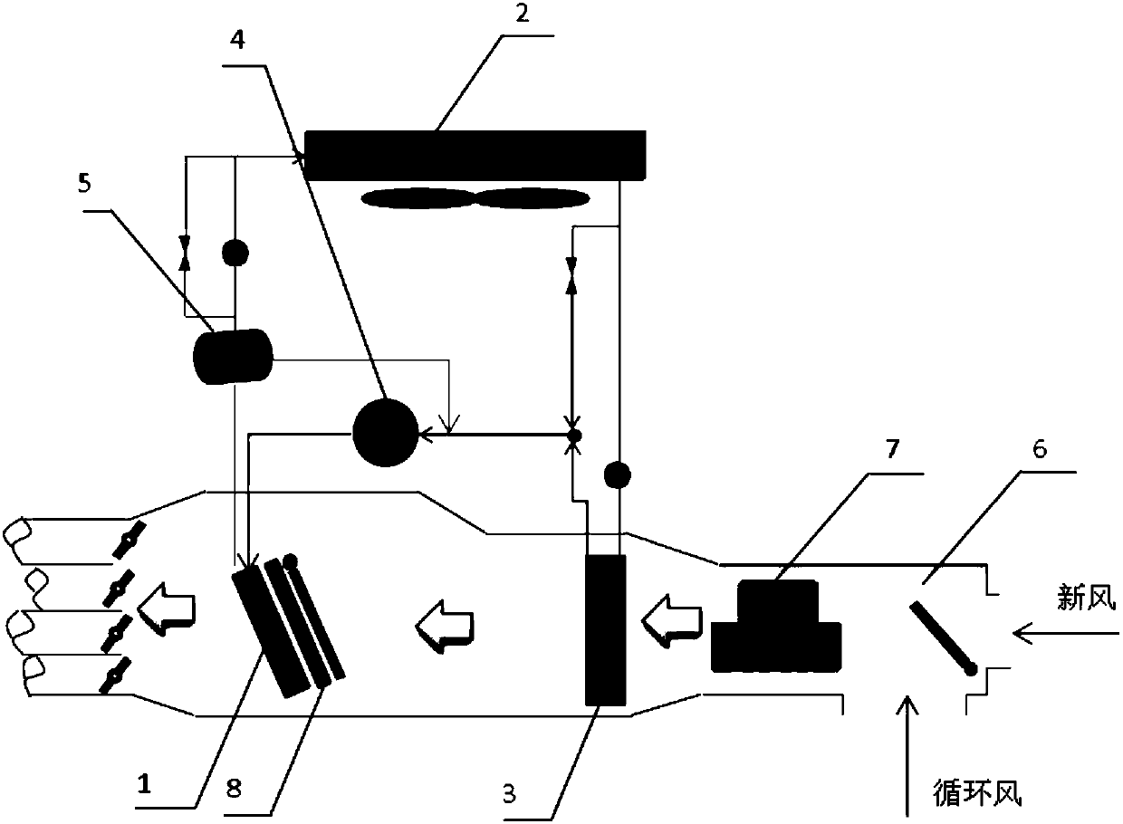
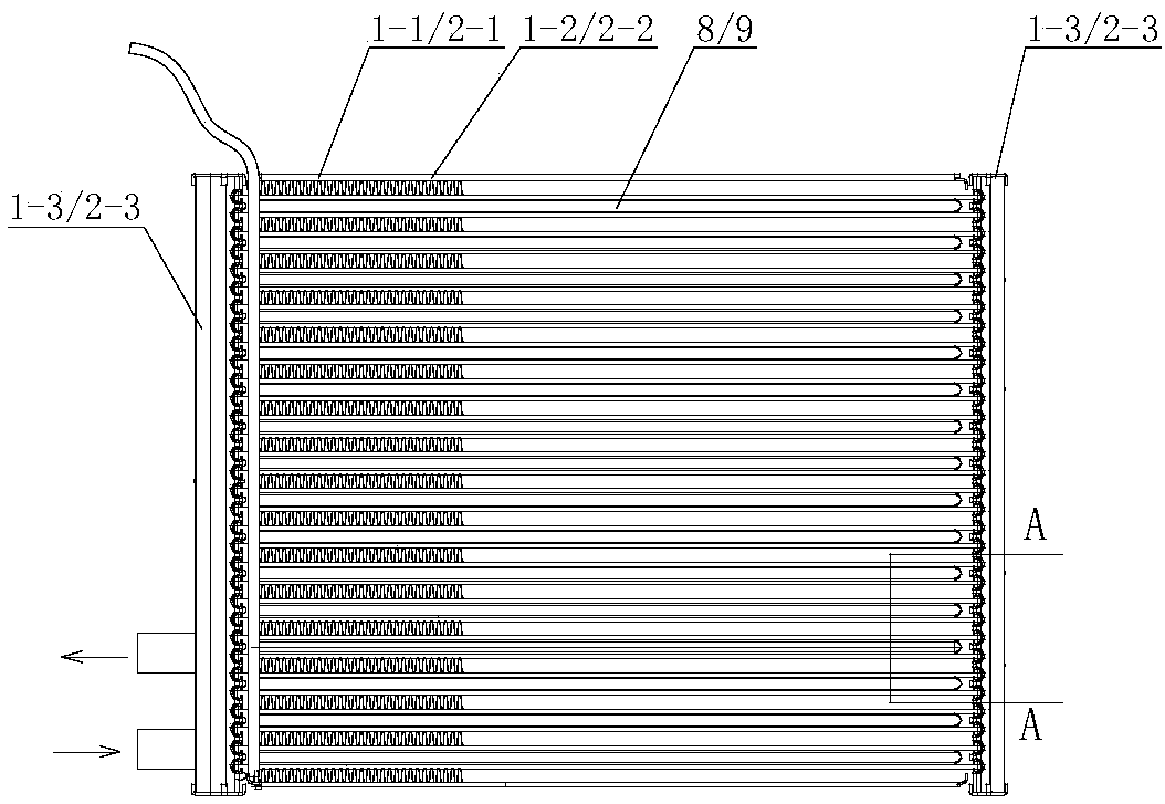
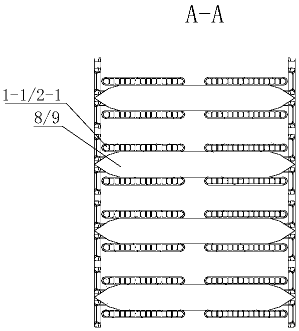
[0026] In order to further understand the invention content, characteristics and effects of the present invention, the following examples are given, and detailed descriptions are as follows in conjunction with the accompanying drawings:

[0027] See Figure 1-9 , an improved heat pump air-conditioning system for automobiles, including an indoor heat exchanger 1, an outdoor heat exchanger 2, an evaporator 3, an electric compressor 4, a gas-liquid separator 5, an air-conditioning box 6, and a blower 7. An air inlet and an air outlet are arranged on the air conditioner body. The blower, the evaporator and the indoor heat exchanger are placed in the air-conditioning box and arranged in sequence along the direction from the air inlet to the air outlet. The indoor heat exchanger, outdoor heat exchanger, evaporator, electric compressor, and gas-liquid separator are connected by pipelines to form a refrigerant circulation loop. The circulation loop can refer to the circulation loop ...


PUM


Abstract

The invention relates to an improved heat pump air-conditioning system used in an automobile. The system includes an indoor heat exchanger, an outdoor heat exchanger, an evaporator, an electric compressor, a gas and liquid separator, an air conditioner body and an air blower; an air inlet and an air outlet are formed in the air conditioner body, and the air blower, the evaporator and the indoor heat exchanger are mounted in the air conditioner body and arranged front and back from an air inlet direction to an air outlet direction in sequence. The indoor heat exchanger, the outdoor heat exchanger, the evaporator, the electric compressor and the gas and liquid separator are connected with one another through a pipe to form a refrigerant circulating loop. The system is characterized in that afirst preheating structure is arranged on an indoor heat exchanger body or a windward upstream side of the indoor heat exchanger. According to the improved heat pump air-conditioning system, by additionally arranging the first preheating structure, when the outdoor environmental temperature is low, a refrigerant in the indoor heat exchanger can be preheated through the first preheating structurebefore a heat pump is started to increase the pressure of the refrigerant in the heat pump system, and it is ensured that the heat pump system can be started at -10 DEG C or in an even colder environment and run stably.

Description

technical field [0001] The invention relates to the field of heat pump air conditioners for cooling and heating of pure electric vehicles, in particular to an improved heat pump air conditioner system for vehicles. Background technique [0002] Electric vehicles do not have the engine to provide waste heat for heating in winter, so the automotive air conditioning system is required not only to have the cooling function in summer, but also to undertake the heating demand in winter. At present, the air conditioning system of electric vehicles on the market is mainly based on PTC electric heating auxiliary air conditioning system, such as Figure 10 As shown, an electric heating auxiliary structure A11 is provided at the rear end of the air outlet side of the evaporator in the air-conditioning compartment. Since electric heating is used, its heating COP (heating energy efficiency ratio) is at most 1, which is extremely energy-consuming and reduces the cruising range of electric...

Claims


Application Information

Patent Timeline
Patent Type & Authority Applications(China)
IPC IPC(8): B60H1/00B60H1/22
CPCB60H1/00392B60H1/005B60H1/2221B60H1/2225
Inventor 陆新林史以奇
Owner TIANJIN SANDEN AUTO AIR CONDITIONING
Why Eureka
Try Eureka