Non-leakage electronic mechanical dual-purpose parking valve group

An electro-mechanical and parking valve technology, applied in the direction of brake components, vehicle components, control valves and air release valves, etc., can solve the problems such as the inability to realize automatic brake input, and achieve the goal of improving vehicle maintainability and safety performance. Effect

Active Publication Date: 2018-05-15
AEROSPACE HEAVY IND
View PDF5 Cites 0 Cited by
  • Summary
  • Abstract
  • Description
  • Claims
  • Application Information

AI Technical Summary

Problems solved by technology

[0005] The embodiment of the present invention provides a non-leakage type electromechanical dual-purpose parking valve group, which is used to solve the problem that the parking brake system needs to be operated to brake the vehicle when the electric vehicle is in operation, and the automatic braking cannot be realized. input function

Method used


Image

  • Non-leakage electronic mechanical dual-purpose parking valve group
  • Non-leakage electronic mechanical dual-purpose parking valve group
  • Non-leakage electronic mechanical dual-purpose parking valve group

Examples


Embodiment 1

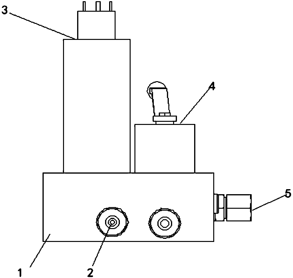
[0032] This embodiment provides a non-leakage electro-mechanical dual-purpose parking valve group, please refer to figure 1 , the parking valve group includes:

[0033] Valve block body 1;

[0034] A one-way valve 2 for controlling the one-way flow of oil, the one-way valve 2 is arranged in the valve block body 1, and the installation direction of the one-way valve 2 is the same as the direction in which the oil flows into the valve block body 1 consistent;

[0035] Specifically, a one-way valve 2 is arranged in the valve block body 1 to control the one-way flow of oil, and the installation direction of the one-way valve 2 is consistent with the direction in which the oil flows into the valve block body 1, that is, the The installation direction of the one-way valve 2 is to allow the oil to flow into the parking valve group, and to prohibit the oil from flowing out from the parking valve group.

[0036] a filter element, the filter element is arranged between the valve bloc...

Embodiment 2

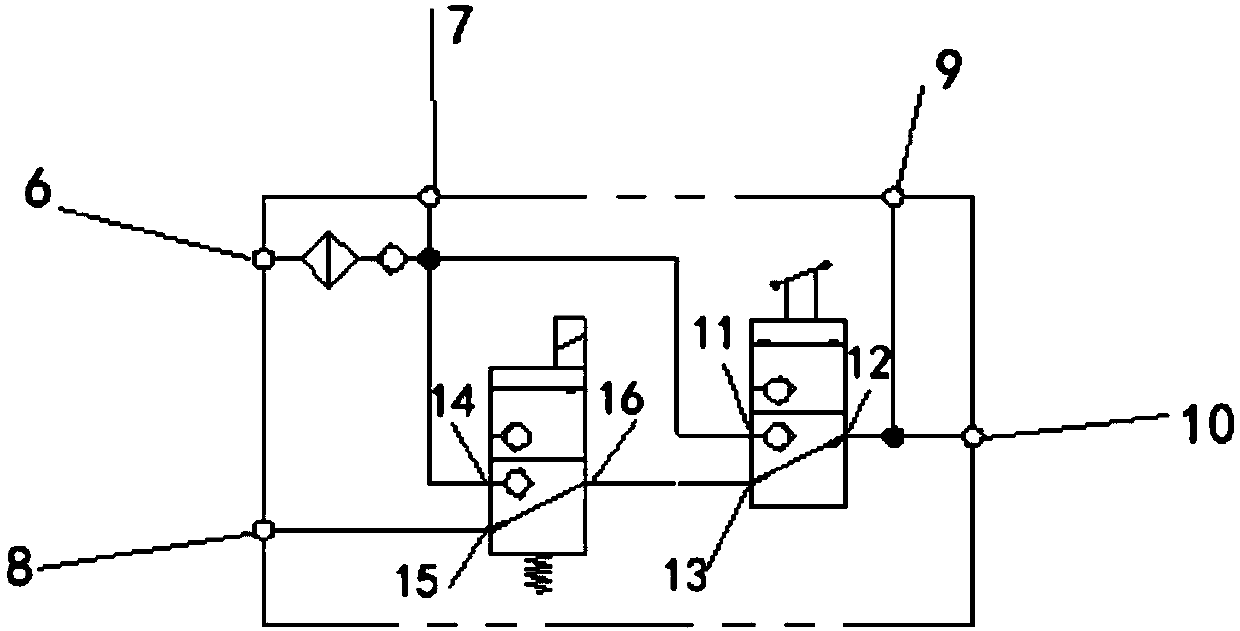
[0050] In order to explain the present invention more clearly, the working principle of a non-leakage electromechanical dual-purpose parking valve group of the present invention is described below, please refer to image 3 ,details as follows:

[0051] Under normal working conditions, the second interface 12 of the plate type three-way ball valve 4 communicates with the third interface 13. When the vehicle is parked, the schematic diagram of the system pipeline connection is as follows: image 3 As shown, the high-pressure oil source enters from the first oil outlet 6 of the parking valve group, flows through the filter element, the check valve 2, and passes through the second oil outlet 7 of the parking valve group to The accumulator is filled with oil, the electromagnetic ball valve 3 is not powered, the electromagnetic first interface 14 of the electromagnetic ball valve 3 is not connected with other oil ports, the oil circuit is cut off, and the first interface 11 of the p...

Embodiment 3

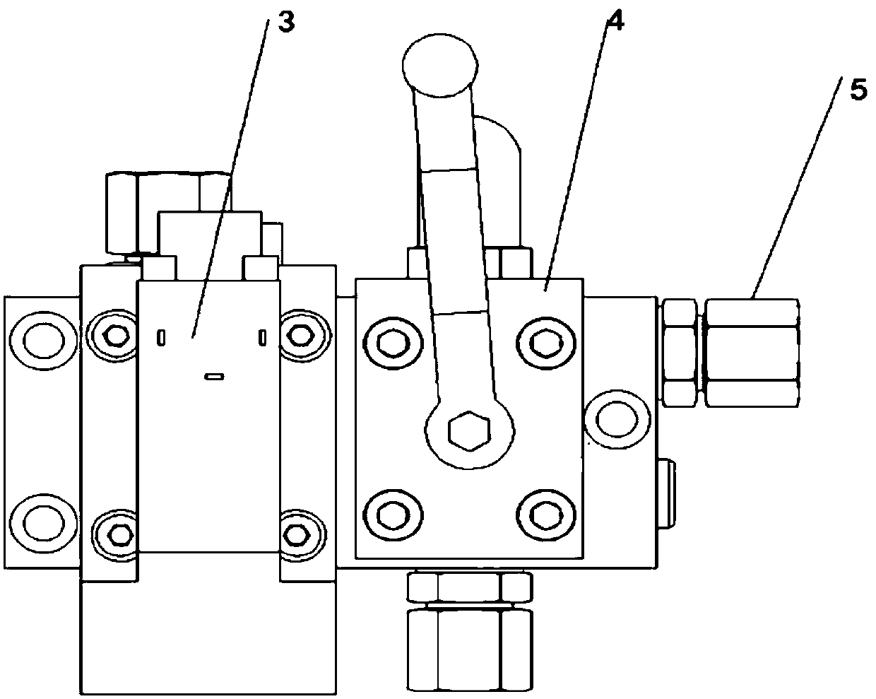
[0053] In order to explain the present invention more clearly, the working principle of a non-leakage electro-mechanical dual-purpose parking valve group of the present invention when the electromagnetic ball valve is energized is described below, please refer to image 3 , Figure 4 ,details as follows:

[0054] Press the vehicle's parking control switch, such as Figure 4 The shown parking valve group is connected to the electric conduction oil circuit of the electromagnetic ball valve. The high-pressure oil source enters through the first oil outlet 6 connected to the valve block body 1, flows through the filter element and the one-way valve 2, and passes through the second outlet of the parking valve group. The oil port 7 is filled with oil to the accumulator connected to it, so the electromagnetic ball valve 3 is energized, and at the same time, the electromagnet in the electromagnetic ball valve 3 is controlled by the parking brake switch, and the electromagnetic secon...


PUM


Abstract

The invention discloses a non-leakage electronic mechanical dual-purpose parking valve group. The parking valve group comprises a valve block body, a single-way valve, a filter core, an electromagnetic ball valve and a plate-type tee ball valve. The single-way valve controls oil liquid to flow in a single direction and is arranged in the valve block body, and the arrangement direction of the single-way valve is identical to the direction of the oil liquid flowing into the valve block body; the filter core is arranged between the valve block body and the single-way valve; the electromagnetic ball valve is arranged above the valve block body and communicated with an outlet of the single-way valve; the plate-type tee ball valve is arranged above the valve block body and arranged parallel to the electromagnetic ball valve, and meanwhile a first connector of the plate-type tee ball valve is communicated with the outlet of the single-way valve. The non-leakage electronic mechanical dual-purpose parking valve group has the advantages that automatic input of a parking braking system and linkage control with a high-voltage electric system are achieved, the safety performance of an automobile is improved, when the automobile fails and a parking electronic control system cannot work, parking braking can be manually removed, and the maintainability of the automobile is improved.

Description

technical field [0001] The technical field of motor vehicles of the present invention particularly relates to a non-leakage type electro-mechanical dual-purpose parking valve group. Background technique [0002] The parking brake system of a traditional engine vehicle usually uses a manual valve to control the parking system, and the parking is released by manually operating the handle. In case of emergency, the parking handle is manually operated to realize the emergency braking function. In working conditions, it is only necessary to realize the vehicle braking function, and for electric vehicles, not only the vehicle braking but also high-voltage power-off are required in emergency situations. [0003] However, in the process of implementing the technical solutions in the embodiments of the present application, the inventors of the present application found that the above-mentioned prior art has at least the following technical problems: [0004] In the prior art, the pa...

Claims


Application Information

Patent Timeline
Patent Type & Authority Applications(China)
IPC IPC(8): B60T15/04B60T15/02
CPCB60T15/028B60T15/04
Inventor 杨楠李欣荣谢宇苏功富钟诚
Owner AEROSPACE HEAVY IND
Why Eureka
Try Eureka