A non-leakage electro-mechanical dual-purpose parking valve group
An electro-mechanical and parking valve technology, which is applied to vehicle parts, brake components, control valves and air release valves, etc., can solve the problem of inability to realize automatic brake input, and achieve the goal of improving vehicle maintainability and safety performance. Effect
- Summary
- Abstract
- Description
- Claims
- Application Information
AI Technical Summary
Problems solved by technology
Method used
Image
Examples
Embodiment 1
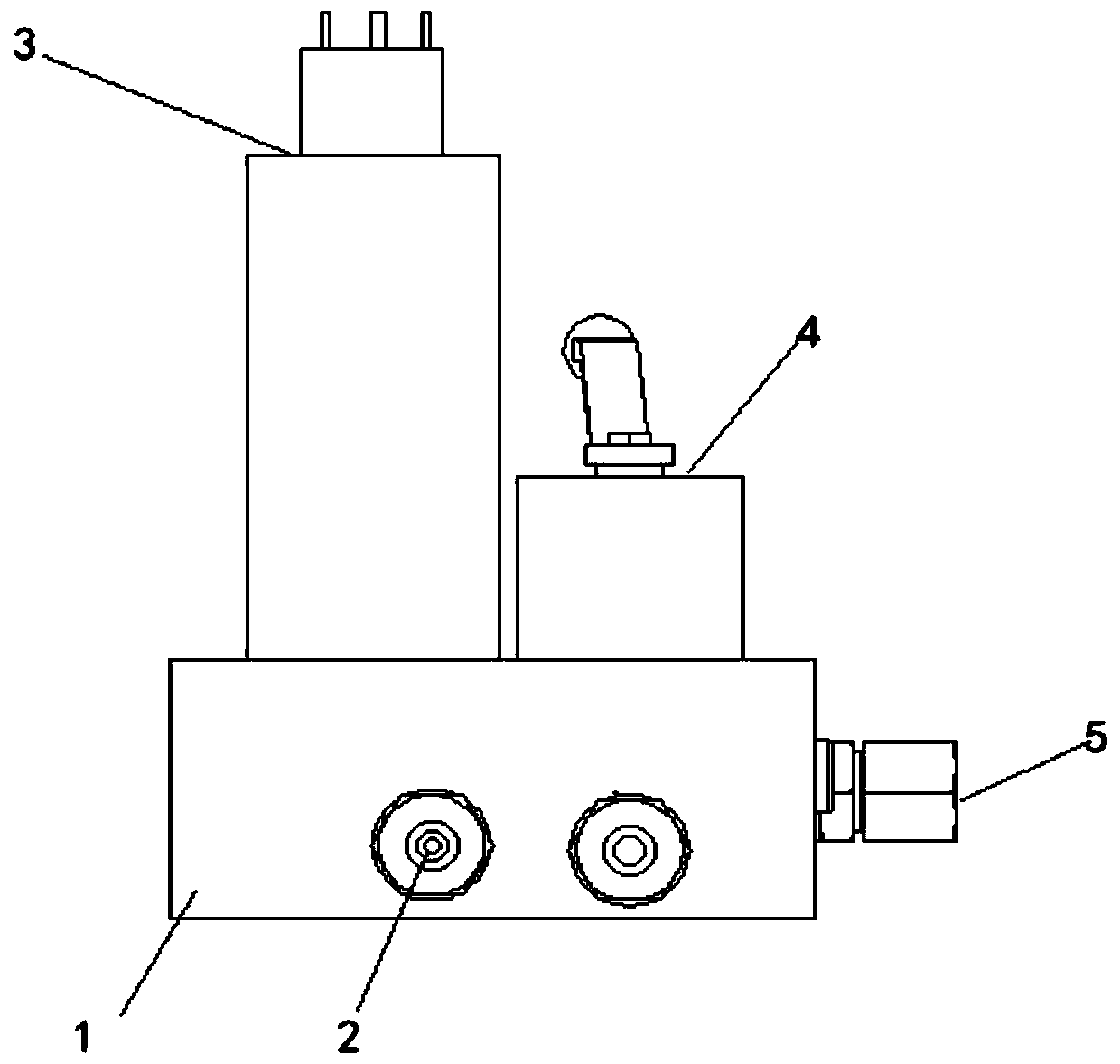
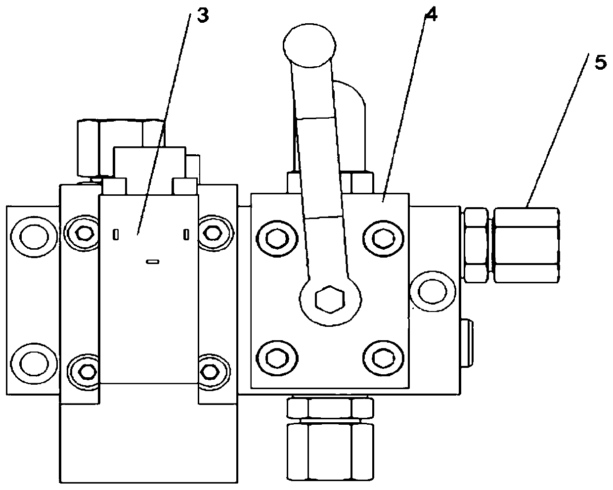
[0032] This embodiment provides a non-leakage electro-mechanical dual-purpose parking valve group, please refer to figure 1 , the parking valve group includes:
[0033] Valve block body 1;
[0034] A one-way valve 2 for controlling the one-way flow of oil, the one-way valve 2 is arranged in the valve block body 1, and the installation direction of the one-way valve 2 is the same as the direction in which the oil flows into the valve block body 1 consistent;
[0035] Specifically, a one-way valve 2 is arranged in the valve block body 1 to control the one-way flow of oil, and the installation direction of the one-way valve 2 is consistent with the direction in which the oil flows into the valve block body 1, that is, the The installation direction of the one-way valve 2 is to allow the oil to flow into the parking valve group, and to prohibit the oil from flowing out from the parking valve group.
[0036] a filter element, the filter element is arranged between the valve bloc...
Embodiment 2
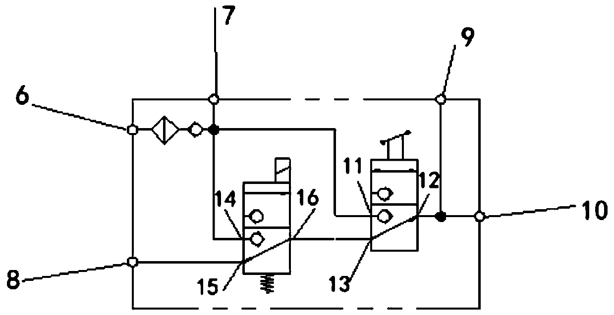
[0050] In order to explain the present invention more clearly, the working principle of a non-leakage electromechanical dual-purpose parking valve group of the present invention is described below, please refer to image 3 ,details as follows:
[0051] Under normal working conditions, the second interface 12 of the plate type three-way ball valve 4 communicates with the third interface 13. When the vehicle is parked, the schematic diagram of the system pipeline connection is as follows: image 3 As shown, the high-pressure oil source enters from the first oil outlet 6 of the parking valve group, flows through the filter element, the check valve 2, and passes through the second oil outlet 7 of the parking valve group to The accumulator is filled with oil, the electromagnetic ball valve 3 is not powered, the electromagnetic first interface 14 of the electromagnetic ball valve 3 is not connected with other oil ports, the oil circuit is cut off, and the first interface 11 of the p...
Embodiment 3
[0053] In order to explain the present invention more clearly, the working principle of a non-leakage electro-mechanical dual-purpose parking valve group of the present invention when the electromagnetic ball valve is energized is described below, please refer to image 3 , Figure 4 ,details as follows:
[0054] Press the vehicle's parking control switch, such as Figure 4 The shown parking valve group is connected to the electric conduction oil circuit of the electromagnetic ball valve. The high-pressure oil source enters through the first oil outlet 6 connected to the valve block body 1, flows through the filter element and the one-way valve 2, and passes through the second outlet of the parking valve group. The oil port 7 is filled with oil to the accumulator connected to it, so the electromagnetic ball valve 3 is energized, and at the same time, the electromagnet in the electromagnetic ball valve 3 is controlled by the parking brake switch, and the electromagnetic secon...
PUM
 Abstract
Description
Claims
Application Information
 - R&D
- Intellectual Property
- Life Sciences
- Materials
- Tech Scout
- Unparalleled Data Quality
- Higher Quality Content
- 60% Fewer Hallucinations
Browse by: Latest US Patents, China's latest patents, Technical Efficacy Thesaurus, Application Domain, Technology Topic, Popular Technical Reports.
© 2025 PatSnap. All rights reserved.Legal|Privacy policy|Modern Slavery Act Transparency Statement|Sitemap|About US| Contact US: help@patsnap.com


