[0039] Example
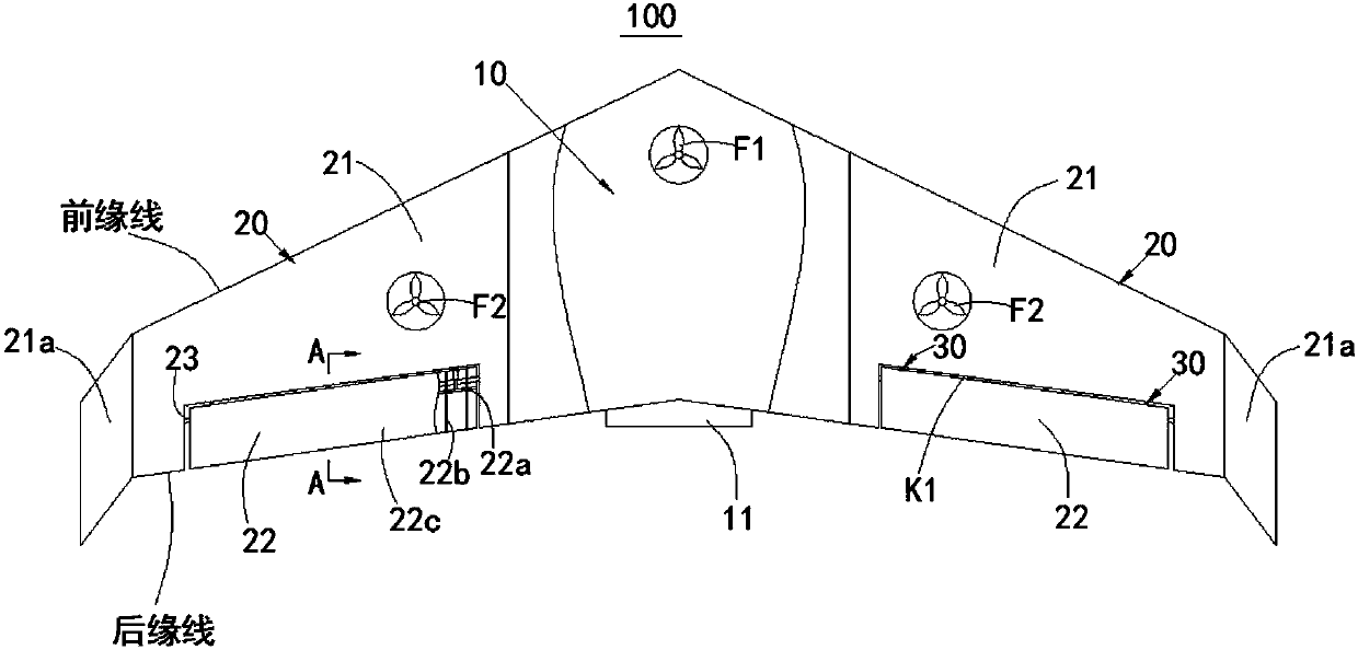
[0040] figure 1 It is a schematic structural diagram of a VTOL fixed-wing drone 100 in an embodiment of the present invention. "VTOL" in the present invention is the abbreviation of "Vertical Take-Off and Landing", meaning "vertical take-off and landing". See figure 1 The VTOL fixed-wing unmanned aerial vehicle 100 of the embodiment of the present invention includes a fuselage 10, and a propeller 11 is provided at the rear end of the fuselage 10; The fuselage 10 and the two fixed wing structures 20 in this embodiment may actually need to be arranged in an integrated form or separately arranged. In this embodiment, the included angle between the front edge lines of the two fixed wing structures 20 is smaller than the included angle between the trailing edge lines of the two fixed wing structures 20, and both included angles are obtuse angles.
[0041] In order to improve the function of the VTOL fixed-wing UAV 100, the head of the fuselage 10 is provided with a first ducted fan F1, and the two fixed-wing structures 20 are respectively provided with a second ducted fan F2. The first ducted fan F1 and the second ducted fan F2 of the two fixed-wing structures 20 are distributed in a triangle. The first ducted fan F1 can assist in controlling the pitch of the head of the fuselage 10, and the two second ducted fans F2 can cooperate to control the roll of the VTOL fixed-wing UAV 100. Of course, the first ducted fan F1 and the second ducted fan F2 are mainly used to assist in adjusting the flight attitude during the take-off and low-speed flight phases of the VTOL fixed-wing UAV 100, and the flight attitude control in the high-speed phase is mainly realized by the fixed-wing structure 20 . The specific arrangement of the fixed wing structure 20 will be described below.
[0042] See also figure 1 , figure 2 In an implementation of this embodiment, the fixed wing structure 20 includes a main wing 21 and an aileron 22 movably hinged to the rear edge cut K1 of the main wing 21. The chord of the main wing 21 is upwardly warped to the outer end to form a blade 21a. The aileron 22 includes a spar 22a, a plurality of ribs 22b spaced along the longitudinal direction of the spar 22a and fixedly connected to the spar 22a, and a skin 22c covering the outer surface of the rib 22b. The aileron 22 is rotatably connected to the main wing 21 through a rotating shaft 23; the axis of the rotating shaft 23 is along the chord direction of the main wing 21 and is located between the spar 22 a and the main wing 21. The main wing 21 is connected with the aileron 22 to the spar 22a through a driving mechanism; the driving mechanism is connected between the bottom surface of the trailing edge cut K1 and the spar 22a, and is used to drive the aileron 22 to swing around the rotating shaft 23. In this embodiment, the rotating shaft 23 passes through the openings on each rib 22b and is fixedly connected to each rib 22b. Both ends of the rotating shaft 23 are hingedly connected to the opposite end surfaces of the rear edge cut K1, and the rotating shaft 23 passes through The position of the hole passing through the rib 22b is between the spar 22a and the trailing edge cut K1.
[0043] In the fixed wing structure 20 in this embodiment, a trailing edge cut K1 is provided on the trailing edge of the main wing 21 to accommodate the aileron 22, so that the overall wing structure is compact and tidy; and, it is used for hinged installation of the shaft of the aileron 22 23 is located in the spar 22a and the main wing 21, which can facilitate the structural setting and driven rotation of the aileron 22; the hinge position of the shaft 23 and the driving mechanism are arranged between the bottom surface of the trailing edge cut K1 and the spar 22a, so that the aileron 22 is driven as a whole The control performance is good; the main wing 21 and the aileron 22 cooperate to improve the overall appearance of the fixed wing structure 20 and avoid the problem of turbulence caused by the external driving mechanism.
[0044] Therefore, the fixed wing structure 20 in the embodiment of the present invention has the beneficial effects of compact structure, neat appearance, good maneuverability, and good flow guiding performance.
[0045] The driving mechanism in this embodiment may be configured to include a plurality of driving cylinder groups 30, the plurality of driving cylinder groups 30 are arranged at intervals along the length of the aileron 22, and are each located in the gap between adjacent ribs 22b. E.g figure 1 Two drive cylinder groups 30 spaced apart from each other are shown in. In other embodiments, the driving mechanism may be configured to include a driving cylinder group 30. The driving cylinder group 30 includes two driving cylinders 31 located on both sides of the rotating shaft 23. One end of each driving cylinder 31 is hingedly connected to the bottom surface of the trailing edge cut K1 and the other One end is hingedly connected to the spar 22a. The driving cylinder group 30 is located at the longitudinal middle position of the aileron 22 and in the gap between two adjacent ribs 22b. The case of one driving cylinder group 30 is not shown.
[0046] See figure 2 In one embodiment, each drive cylinder group 30 includes two drive cylinders 31 located on both sides of the rotating shaft 23, one end of each drive cylinder 31 is hingedly connected to the bottom surface of the trailing edge cut K1, and the other end is hingedly connected to the spar 22a. The two drive cylinders 31 of each drive cylinder group 30 are parallel to each other when the aileron 22 is in the initial position. The initial position mentioned here refers to the state where the aileron 22 and the main wing 21 are not relatively rotated, and the aileron 22 and the main wing 21 are coplanar. In this embodiment, one of the driving cylinders 31 extending and the other retracting can drive the spar 22a to drive the entire aileron 22 to rotate around the shaft 23 to a certain angle. The driving cylinder 31 here can be a driving cylinder. The upward or downward swing of the aileron 22 is realized by two driving cylinders located on both sides of the rotating shaft 23, and the control performance is significantly better than the swing control of the aileron 22 in the prior art.
[0047] In another embodiment, see image 3 The two driving cylinders 31 of each driving cylinder group 30 are hingedly connected to the main wing 21 at the same point, and the spar 22a is hingedly connected at two spaced apart points; the rotating shaft 23 is located inside the triangle formed by the two driving cylinders 31 and the spar 22a. In this form, the extension/retraction amount of the two driving cylinders 31 when the spar 22a is deflected at a certain angle can be calculated by the cosine theorem of triangles for control.
[0048] Therefore, the fixed wing structure 20 in the embodiment of the present invention has the beneficial effects of compact structure, neat appearance, good maneuverability, and good flow guiding performance.