
Anti-dust worm-gear lifting machine with self-control stroke

A worm gear and elevator technology, applied in the elevator field, can solve the problems of inaccurate control of the lifting position, low transmission accuracy, affecting the worm gear and worm transmission, etc., and achieves the effects of good performance, high degree of control, and long service life.

Inactive Publication Date: 2018-05-15
JIANGSU TAILONG MACHINERY GRP CO CO LTD
View PDF4 Cites 4 Cited by
  • Summary
  • Abstract
  • Description
  • Claims
  • Application Information

AI Technical Summary

Problems solved by technology

However, due to the axial gap in the trapezoidal thread transmission pair, the transmission accuracy of the elevator is not high when it is working, and the lifting position cannot be accurately controlled. At the same time, the lifting screw is exposed outside, and dust can easily enter the reducer and affect the worm gear transmission.

Method used


Image

  • Anti-dust worm-gear lifting machine with self-control stroke

Examples


Embodiment Construction

[0009] Further description will be made below in conjunction with the accompanying drawings.

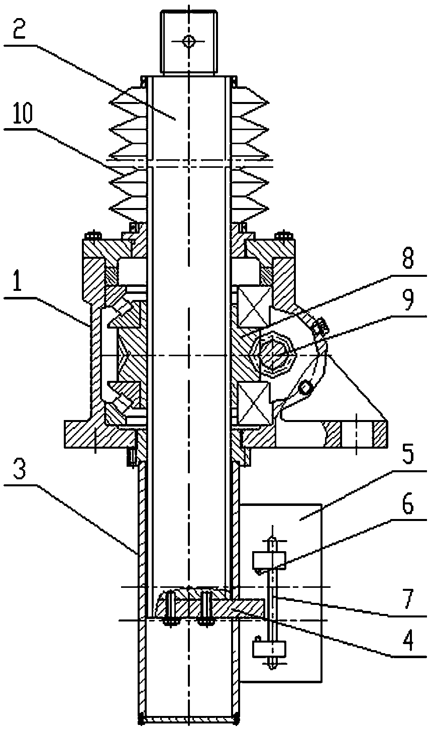
[0010] figure 1 As shown: a dust-proof stroke self-control worm gear elevator includes a box body 1, a lifting screw rod 2, a limit lifting box body 3, an anti-rotation slider 4, a limit mounting plate 5, a travel switch 6, a displacement sensor 7, a drive Worm wheel 8, driving worm 9, telescoping sleeve 10. Lifting screw mandrel 2 is pierced and connected on the casing 1 up and down, and the lifting screw mandrel extends downwards and is connected in the limit lift box 3 body below the box body and its bottom connects anti-rotation slide block 4, and the limit lift box 3 body outsides are arranged. The limit mounting plate 5 is provided with upper and lower travel switches 6 and displacement sensors 7 with adjustable relative positions up and down on the limit mounting plate, and the anti-rotation slider 4 is correspondingly arranged between the upper and lower travel switches. Th...


PUM


Abstract

The invention relates to an anti-dust worm-gear lifting machine with a self-control stroke. A lifting screw rod is up-and-down connected onto a tank in a penetrating way, and downwards stretches intoa limiting lifting tank connected under the tank; an anti-rotation sliding block is connected to the bottom part of the lifting screw rod; a limiting installation plate is arranged on the outer side of the limiting lifting tank; an upper stroke switch and a lower stroke switch with adjustable up-and-down relative positions are arranged on the limiting installation plate; the anti-rotation slidingblock is correspondingly arranged between the upper stroke switch and the lower stroke switch; the lifting screw rod is connected onto a drive worm wheel connected into the tank in a penetrating way;a drive worm is meshed with the drive worm wheel; the lifting screw rod upwards stretches out of the tank; a telescopic sleeve pipe is sleeved to the stretching part in a sealing way; and a displacement sensor corresponding to a limiting sliding block is further arranged on the limiting installation plate. The anti-dust worm-gear lifting machine with the self-control stroke is simple in structure,can effectively control lifting formation, and prevents dust from entering so as to influence the lifting operation.

Description

technical field [0001] The invention relates to a lift, in particular to a dust-proof stroke automatic control worm gear lift. Background technique [0002] Worm gear screw lifts are widely used in various equipment or instruments that need to move up and down. At present, domestic worm gear screw lifts use worm gears for deceleration, and the screw is telescopically moved through the trapezoidal thread transmission pair between the worm wheel and the screw. Realize up and down. However, due to the axial gap in the trapezoidal thread transmission pair, the transmission accuracy of the elevator is not high when it is working, and the lifting position cannot be accurately controlled. At the same time, the lifting screw is exposed outside, and dust can easily enter the reducer and affect the worm gear transmission. Contents of the invention [0003] In view of the above shortcomings, the present invention provides a dust-proof stroke self-control worm gear elevator with simp...

Claims


Application Information

Patent Timeline
Patent Type & Authority Applications(China)
IPC IPC(8): B66F3/18
CPCB66F3/18
Inventor 赵诗韵胡美娟李素珍张介禄
Owner JIANGSU TAILONG MACHINERY GRP CO CO LTD
Learn More