An unmanned bridge detection and maintenance device
A bridge detection and bridge technology, applied in bridges, bridge construction, bridge parts, etc., can solve the problems that the detection device cannot pass through street lights, bridge cables, manual maintenance, etc., so as to reduce the negative impact of traffic, reduce the size of the structure, The effect of ensuring the stability of the equipment
- Summary
- Abstract
- Description
- Claims
- Application Information
AI Technical Summary
Problems solved by technology
Method used
Image
Examples
Embodiment 1
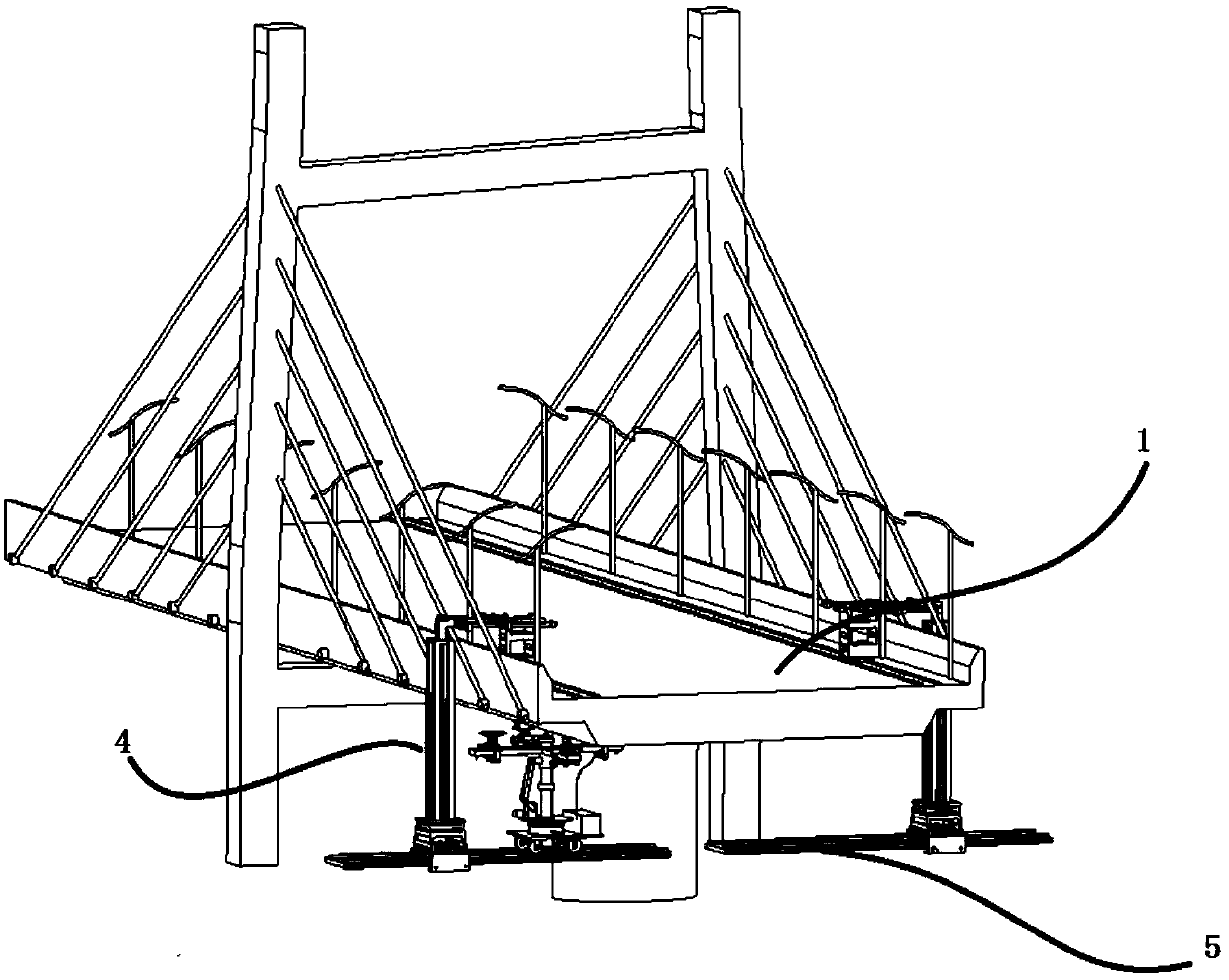
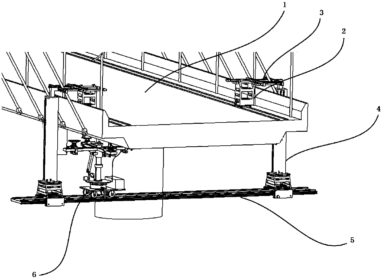
[0048] Such as figure 1 , 2 As shown, the present embodiment provides a bridge detection device, including: a bridge deck running mechanism, including: a drive car 2 is installed longitudinally along the direction of travel on the non-traffic lanes on both sides of the bridge 1, and the drive car 2 can be Walk along the direction of travel of the non-traffic lane; the driving car 2 is provided with a counterweight and a motor, and the motor drives the driving car 2 to advance along the longitudinal direction of the bridge.
[0049] The specific structure of the bridge deck running mechanism in this embodiment may be the structure of the bridge deck running mechanism disclosed in the application number 2016100127105.
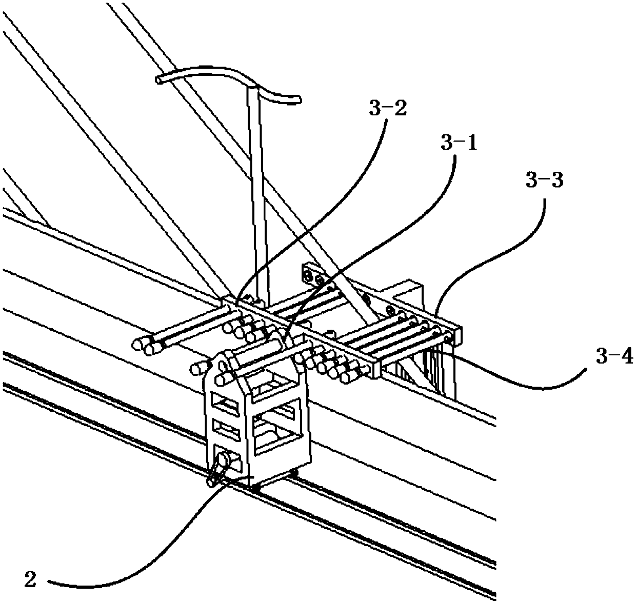
[0050] Connecting mechanism, each driving car 2 is connected with a connecting mechanism respectively, and described connecting mechanism comprises transverse connecting arm 3 and vertical connecting arm 4, and one end of described transverse connecting arm 3 is...
Embodiment 2
[0061] On the basis of Embodiment 1, this embodiment provides two guide frames 16-1 vertically on both sides of the round table 7, and a sliding hole is provided at the lower end of the guide frame 16-1, and the sliding hole passes through The bolts are fitted with sliding wheels 16 - 2 cooperating with the side surfaces of the transverse rails 5 . In this way, the pressing force of the guide wheel can be adjusted through the bolts to prevent the working mechanism from turning over.
Embodiment 3
[0063] Such as Figure 5 , this embodiment provides a lifting structure on the basis of Embodiment 1, including a third motor, a second reducer, a crank 8-1, a rocker 8-2, a lifting guide rail 8-3, and a lifting slider 8-4, Lifting guide rail 8-3 is vertically installed on the center of the upper surface of round table 7, and the third motor is connected with one end of crank 8-1 through the second speed reducer, and the other end of crank 8-1 is connected with the end of rocking bar 8-2. One end is connected, the other end of the rocker 8-2 is connected with the lifting slider 8-4, the lifting slider 8-4 is installed on the lifting guide rail 8-3, and the cross-shaped working arm 9 is horizontally arranged on the lifting slider 8-4 on.
[0064] In this embodiment, the third motor and the reducer are installed at the edge of the round table 7, thus forming a crank slider system. Driven by the third motor, the lifting slider slides on the lifting guide rail to realize height a...
PUM
 Abstract
Description
Claims
Application Information
 - R&D
- Intellectual Property
- Life Sciences
- Materials
- Tech Scout
- Unparalleled Data Quality
- Higher Quality Content
- 60% Fewer Hallucinations
Browse by: Latest US Patents, China's latest patents, Technical Efficacy Thesaurus, Application Domain, Technology Topic, Popular Technical Reports.
© 2025 PatSnap. All rights reserved.Legal|Privacy policy|Modern Slavery Act Transparency Statement|Sitemap|About US| Contact US: help@patsnap.com


