Eureka AIR delivers breakthrough ideas for toughest innovation challenges, trusted by R&D personnel around the world.

Tunnel secondary lining formwork trolley foot sealing structure and its installation method

A technology of secondary lining and formwork trolley, applied in tunnel lining, tunnel, wellbore lining, etc., can solve the problems of poor surface flatness of the root of secondary lining, lack of attention, explosion mode, etc., so as to improve the quality of concrete and avoid explosion. The effect of reducing the mold phenomenon and reducing the degree of misalignment

Active Publication Date: 2019-04-23
CHINA 19TH METALLURGICAL CORP
View PDF5 Cites 0 Cited by
  • Summary
  • Abstract
  • Description
  • Claims
  • Application Information

AI Technical Summary

Problems solved by technology

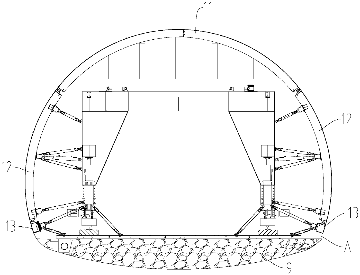
[0002] At present, the tunnel foot type secondary lining formwork trolley such as figure 2 The top form 11 shown along its circumference, the side forms 12 connected to the top form 11 on both sides, the hanging form 13 and the end formwork hoisted at the lower end of the side form 12, and the lower end of the hanging form and the top surface of the inverted arch There is a distance A of 20cm between them. For this distance, the relevant construction personnel did not pay attention to it when sealing the mold, resulting in poor surface smoothness of the root of the second lining at the tunnel site, and frequent mold explosions.

Method used


Image

  • Tunnel secondary lining formwork trolley foot sealing structure and its installation method
  • Tunnel secondary lining formwork trolley foot sealing structure and its installation method

Examples


Embodiment Construction

[0023] Below in conjunction with accompanying drawing and embodiment the present invention is described further as follows:

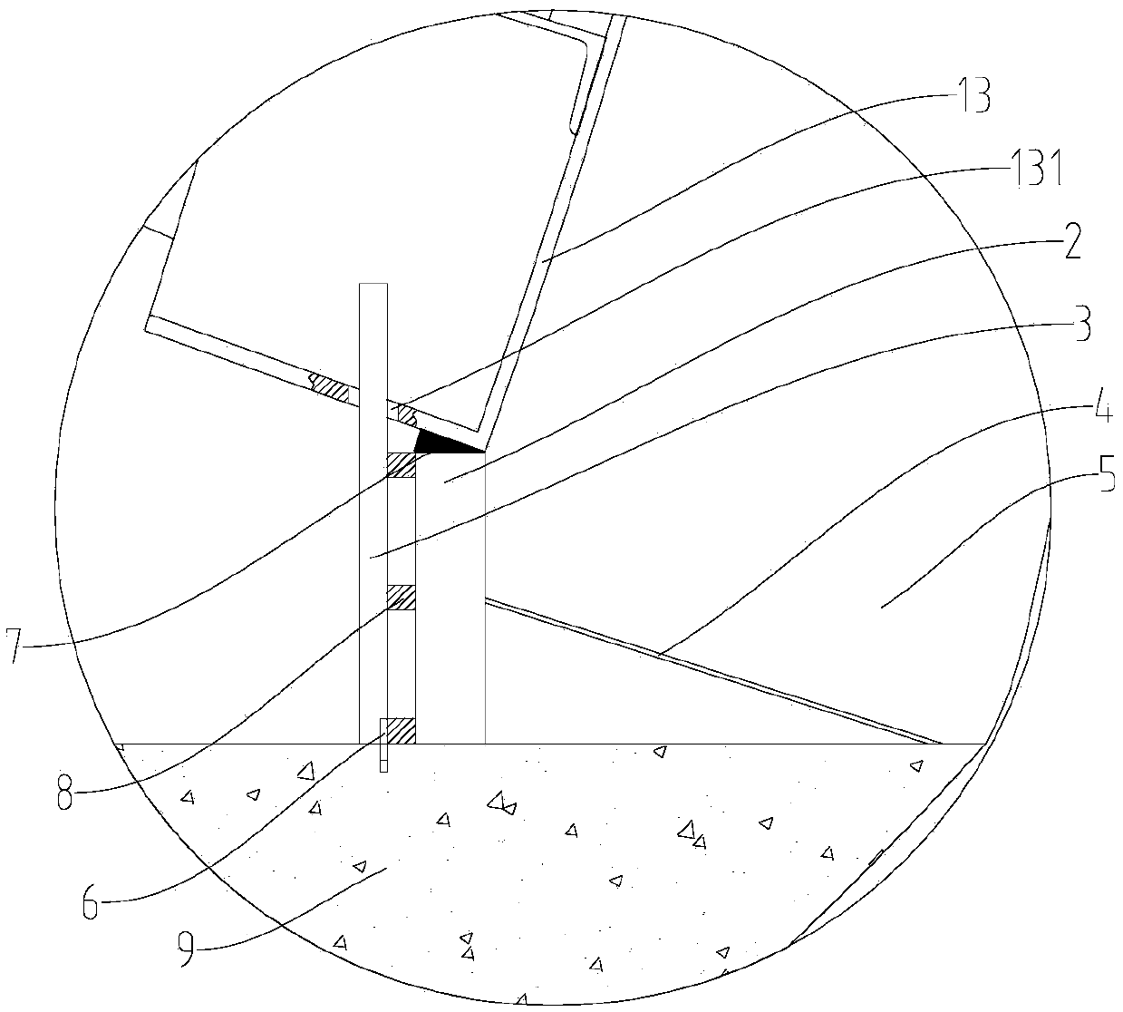
[0024] Tunnel secondary lining formwork trolley foot sealing structure, such as figure 1 As shown, it includes the foot cover formwork 2 located between the hanging form 13 of the tunnel secondary lining formwork trolley and the top surface of the inverted arch, the outer support column 3 located outside the foot cover formwork 2 and the inner support located inside the foot cover formwork 2 Part 4; the top of the working surface of the foot-sealing template 2 extends to the lower end of the working surface of the hanging mold 13, and the bottom extends downward to the surface of the inverted arch; the upper end of the outer support column 3 is installed on the lower end of the hanging mold 13, and the lower end is installed on the inverted arch; one end of the inner support 4 is supported on the foot cover template 2, and the other end is against the ...


PUM


Abstract

The invention discloses a tunnel secondary lining formwork trolley foot sealing structure, and belongs to the field of formwork construction. The phenomena of faulting of slab ends and formwork explosion are avoided, and the secondary lining root concrete quality is controlled. The structure comprises a foot sealing formwork, an outer supporting column located on the outer side of the foot sealingformwork and an inner supporting piece located on the inner side of the foot sealing formwork; the top end of the working face of the foot sealing formwork extends to the lower end of the working face of a hanging formwork, and the bottom end of the working face of the foot sealing formwork extends downwards to the surface of an inverted arch; the upper end of the outer supporting column is installed at the lower end of the hanging formwork, and the lower end of the outer supporting column is installed on the inverted arch; one end of the inner supporting piece is supported on the foot sealing formwork, and the other end of the inner supporting piece abuts against the surface of the inverted arch; the outer supporting column and the inner supporting piece clamp the foot sealing formwork relatively. The distance between the top face of the inverted arch and the hanging formwork is sealed through the foot sealing formwork, the degree of faulting of slab ends is lowered, the phenomenon of formwork explosion is avoided, and the secondary lining root concrete quality is improved. The tunnel secondary lining formwork trolley foot sealing structure is simple in installation method, few formwork tools are input, the structure is repeatedly used, and the structure is convenient to use and capable of saving time and materials.

Description

technical field [0001] The invention belongs to the field of formwork construction, in particular to a foot sealing structure of a formwork trolley for secondary lining of a tunnel and an installation method thereof. Background technique [0002] At present, the tunnel foot type secondary lining formwork trolley such as figure 2 The top form 11 shown along its circumference, the side forms 12 connected to the top form 11 on both sides, the hanging form 13 and the end formwork hoisted at the lower end of the side form 12, and the lower end of the hanging form and the top surface of the inverted arch There is a distance A of 20cm between them. For this distance, the relevant construction personnel did not pay attention to it when sealing the mold, resulting in poor surface flatness of the root of the second lining at the tunnel site, and frequent mold explosions. Contents of the invention [0003] The technical problem to be solved by the present invention is to provide a f...

Claims


Application Information

Patent Timeline
Patent Type & Authority Patents(China)
IPC IPC(8): E21D11/10
CPCE21D11/102
Inventor 夏孝军李玲娇李吉周泽林
Owner CHINA 19TH METALLURGICAL CORP
Why Eureka
Eureka Blog
Learn More