
A controllable and intelligent magnetorheological pulse generator

A pulse generator and magnetorheological technology, applied in shock absorbers, shock absorbers, impact testing, etc., can solve the problems of slow response speed of hydraulic system and difficulty in real-time control.

Active Publication Date: 2019-06-11
WUHAN UNIV OF TECH
View PDF7 Cites 0 Cited by
  • Summary
  • Abstract
  • Description
  • Claims
  • Application Information

AI Technical Summary

Problems solved by technology

Secondly, the hydraulic servo system is used more often to control the movement of hydraulic actuators to realize the control of its motion acceleration. However, due to the slow response speed of the hydraulic system (especially the hydraulic system with large flow rate), it is difficult to achieve real-time control.

Method used


Image

  • A controllable and intelligent magnetorheological pulse generator
  • A controllable and intelligent magnetorheological pulse generator
  • A controllable and intelligent magnetorheological pulse generator

Examples


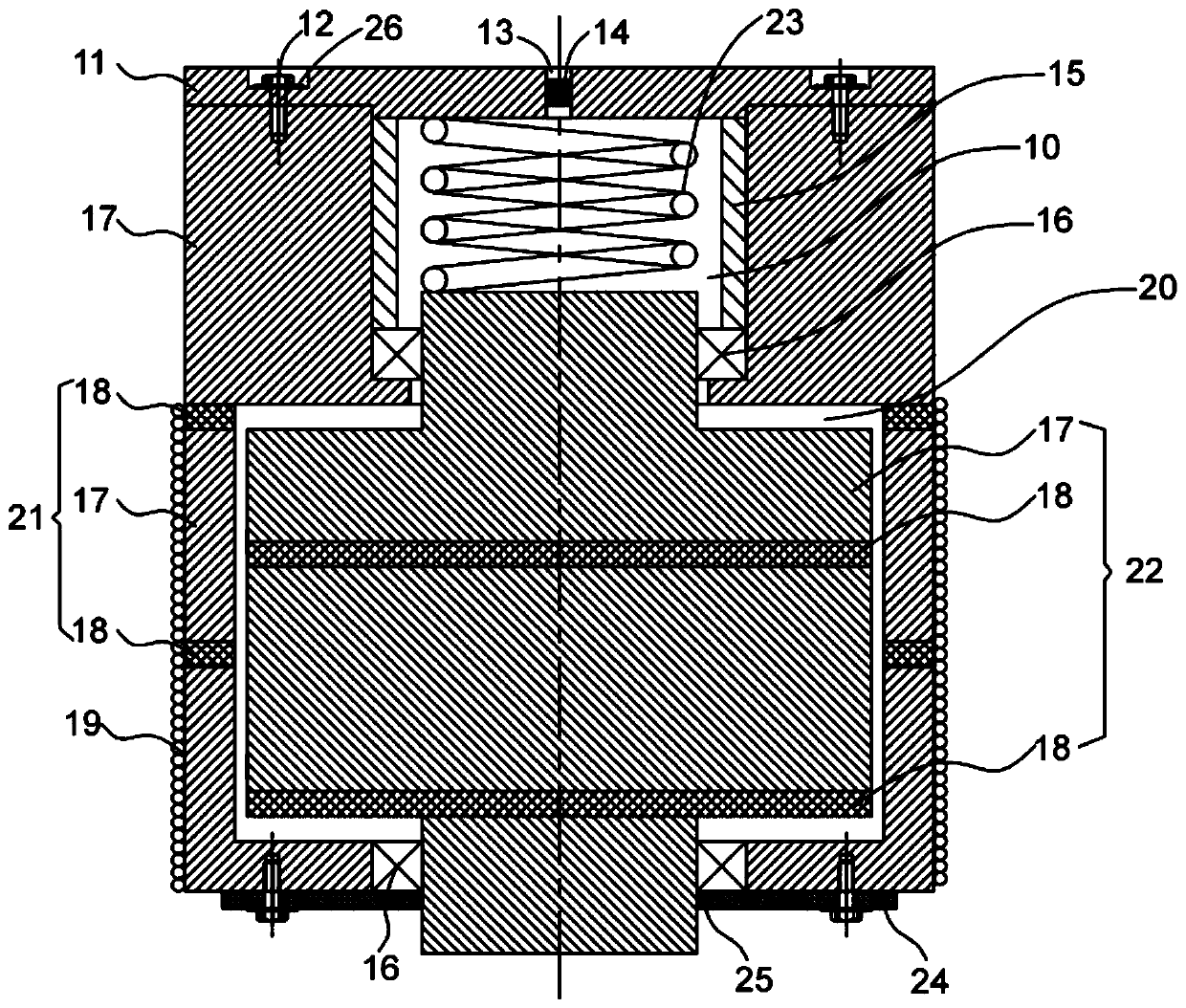
Embodiment Construction

[0027] The present invention will be further described in detail below in conjunction with the accompanying drawings and specific embodiments.

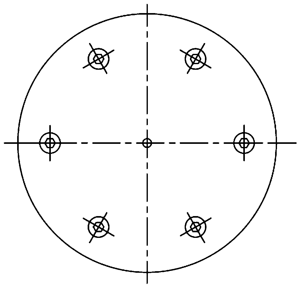
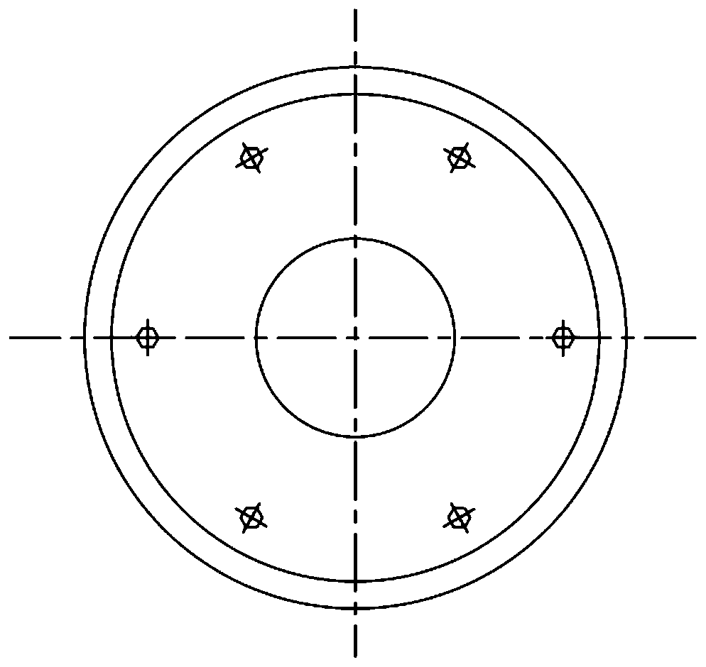
[0028] Such as Figure 1-Figure 4 As shown, a controllable intelligent magneto-rheological pulse generator includes two upper and lower chambers A and B, and a piston 22 and an elastic body 23 located in the chambers.

[0029] The top of chamber A is sealed, specifically by the upper top cover 11, which is connected with the housing of chamber A by screws 12, and a lock washer 26 is installed between the screws 12 and the housing. The upper top cover 11 is provided with a through hole 13 to ensure that the internal and external air pressure remains consistent when the piston 22 moves, and the through hole 13 is provided with a dustproof plug 14 to isolate external dust from entering. Of course, the upper top cover 11 and the housing of the A chamber can be integrally formed.

[0030] The upper end of the piston 22 and the seal ring ...


PUM


Abstract

The present invention relates to a controllable intelligent magnetorheological pulse generator. The generator comprises an upper chamber A, a lower chamber B, a piston (22) and an elastic body (23) which are located inside the chambers respectively; the housing (21) and the piston (22) of the chamber B (20) are formed by solidifying magnetizers (17) and a plurality of magnetic separation bodies (18); a gap between the chamber B (20) and the piston (22) is filled with a magnetorheological fluid; the housing (21) outside the chamber B (20) is wound with an electromagnetic coil (19) which is connected with alternating current; a magnetic field generated by the electromagnetic coil (19) passes through vertically a gap between the top of the chamber B (20) and the piston (22); the elastic body(23) is located in the chamber A (10); and one end of the elastic body (23) is connected with the upper end portion of the piston (22), and the other end of the elastic body (23) is connected with thetop of the chamber A (10). According to the controllable intelligent magnetorheological pulse generator of the invention, the strength of the magnetic field can be changed through changing the magnitude of current, so that the stiffness and damping of the magnetorheological fluid can be changed, and the top output waveforms of the chamber A can be controlled to be pulse waveforms.

Description

technical field [0001] The invention relates to a pulse waveform generator, in particular to a pulse generator controlled by magneto-rheological fluid. Background technique [0002] With the rapid development of today's information age, there are more and more types of electronic products, and the internal structure is becoming more and more complex. With the gradual popularization of electronic products in daily life, people will use electronic products for various leisure activities. Interaction, which means that electronic products must be able to work normally in various environments, so generally electronic products are required to do various tests when they leave the factory, simulating the working conditions in various situations in the real environment. [0003] There are various forms of mechanical force on electronic equipment in the actual working environment, such as vibration, impact, centrifugal force, friction force generated by mechanism movement, etc. Among ...

Claims


Application Information

Patent Timeline
Patent Type & Authority Patents(China)
IPC IPC(8): G01M7/02G01M7/08H02K44/02F16F9/53
CPCF16F9/535F16F2224/045F16F2228/066G01M7/022G01M7/08H02K44/02
Inventor 王贡献余彬彬孙晖
Owner WUHAN UNIV OF TECH
Learn More