
Testing device for measuring damping vibration reduction effect of turbine movable blade

A test device and moving blade technology, which is applied in the direction of measuring device, vibration test, mechanical parts test, etc., can solve the problems that the damping effect of the turbine moving blade cannot be obtained, the force state cannot be simulated, and the high-frequency vibration table cannot be installed.

Active Publication Date: 2018-05-15
CHINA AIRPLANT STRENGTH RES INST
View PDF7 Cites 2 Cited by
  • Summary
  • Abstract
  • Description
  • Claims
  • Application Information

AI Technical Summary

Problems solved by technology

[0003] Existing tests on the damping and vibration reduction effect of turbine rotor blades can only fix the loading device on the ground and use a hammer or vibrator for excitation, which cannot be installed on a high-frequency vibration table, so the work of turbine rotor blades and damping cannot be simulated Under load and working state, it is impossible to avoid the impact of the additional mass and additional stiffness of the hammer or vibrator on the test results by using the existing test method to measure the damping of the turbine blade, and it is impossible to obtain a more in line with the actual working state. The damping effect of turbine blades is not conducive to the design and research of engine turbine blade damping

Method used


Image

  • Testing device for measuring damping vibration reduction effect of turbine movable blade
  • Testing device for measuring damping vibration reduction effect of turbine movable blade
  • Testing device for measuring damping vibration reduction effect of turbine movable blade

Examples


Embodiment Construction

[0025] In order to make the objectives, technical solutions and advantages of the present invention clearer, the technical solutions in the embodiments of the present invention will be described in more detail below in conjunction with the drawings in the embodiments of the present invention. In the drawings, the same or similar reference numerals denote the same or similar elements or elements having the same or similar functions throughout. The described embodiments are some, but not all, embodiments of the invention. The embodiments described below by referring to the figures are exemplary and are intended to explain the present invention and should not be construed as limiting the present invention. Based on the embodiments of the present invention, all other embodiments obtained by persons of ordinary skill in the art without creative efforts fall within the protection scope of the present invention. Embodiments of the present invention will be described in detail below ...


PUM


Abstract

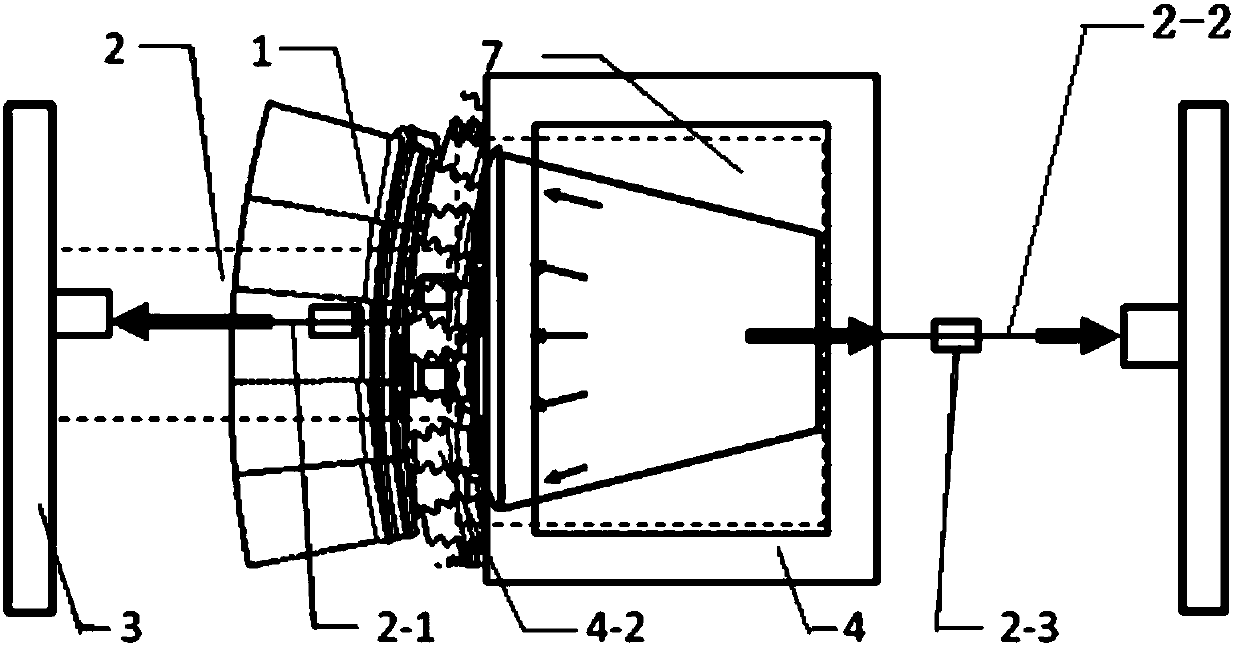
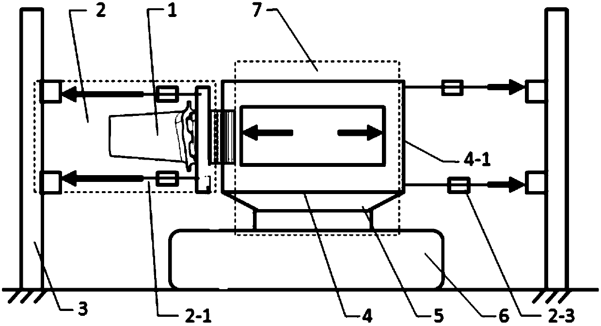
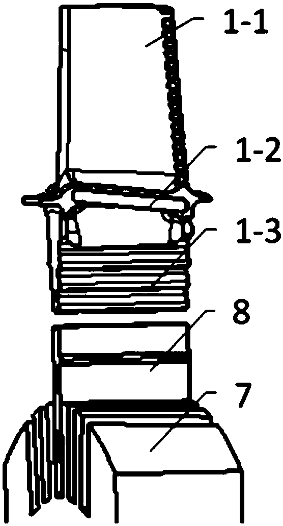
The invention discloses a test device for measuring the damping vibration reduction effect of a turbine movable blade, and belongs to the technical field of turbine movable blade testing. The testingdevice includes a first loading mechanism for applying a centrifugal load to the blade portion of the turbine movable blade, a second loading mechanism for applying a centrifugal load to the damping part of the turbine movable blade, a vibration mechanism for providing vibration, a clamp for clamping the blade and an acceleration sensor for measuring the vibration effect. The loading device can guarantee that two loading mechanisms are independent from each other when carrying out loading work, and no coupling phenomenon occurs, and the problem of damping measurement under the working state ofthe existing turbine movable blade can be solved, the technical support is provided for design and research of the movable blade damping of the engine, and a guarantee is provided for the research ofthe safety and reliability of the engine.

Description

technical field [0001] The invention belongs to the technical field of turbine rotor blade testing, in particular to a test device for measuring the damping and vibration reduction effect of turbine rotor blades. Background technique [0002] Due to the harsh working environment of the turbine rotor blades, the large aerodynamic force and unstable excitation load, in order to avoid the resonance caused by the forced vibration of the blades, the method of increasing damping is adopted to suppress the response of the blades and reduce the vibration stress. Therefore, It is necessary to study the influence of the damping block on the vibration characteristics of the blade when the blade is subjected to centrifugal force, that is, the vibration reduction effect of the damping block needs to be studied. [0003] Existing tests on the damping and vibration reduction effect of turbine rotor blades can only fix the loading device on the ground and use a hammer or vibrator for excita...

Claims


Application Information

Patent Timeline
IPC IPC(8): G01M7/02G01M13/00
CPCG01M7/025G01M7/027G01M13/00
Inventor 秦洁黄文超燕群高翔
Owner CHINA AIRPLANT STRENGTH RES INST
Learn More