
Assembling method for preservative oil immersion type amorphous transformer iron core

A technology of amorphous iron core and assembly method, which is applied in inductance/transformer/magnet manufacturing, magnetic core manufacturing, electrical components, etc., can solve problems such as winding short circuit, affecting the quality of amorphous transformer, etc., so as to reduce the probability of short circuit and reduce The probability of occurrence, the effect of ensuring quality

Active Publication Date: 2018-05-15
JIANGSU HONGYUAN ELECTRIC
View PDF4 Cites 0 Cited by
  • Summary
  • Abstract
  • Description
  • Claims
  • Application Information

AI Technical Summary

Problems solved by technology

[0002] When the amorphous alloy transformer is running, there will be scattered debris on the surface of the iron core. The debris will move to the winding with the circulating oil. When the transformer is running, the debris on the winding will discharge, causing the winding to be short-circuited, seriously affecting the quality of the amorphous transformer.

Method used


Image

  • Assembling method for preservative oil immersion type amorphous transformer iron core
  • Assembling method for preservative oil immersion type amorphous transformer iron core

Examples


Embodiment 1

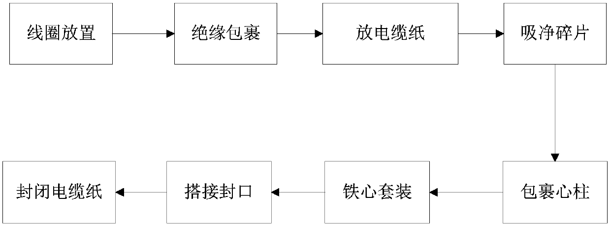
[0031] Such as figure 1 As mentioned above, a protective oil-immersed amorphous transformer core assembly method disclosed in the embodiment of the present invention includes the following steps:

[0032] (1) The qualified coils on the roller table will be hoisted on the brackets of the assembly table according to the phase sequence;

[0033] (2) Wrap the contact part of the coil with the amorphous core with cable paper;

[0034] (3) Place the upper and lower yoke cable papers of the integral iron core in the inner frame of the coil, and fix the cable papers with adhesive tape along the coil window;

[0035] (4) Hoist the amorphous iron core to the hydraulic flatbed truck in sequence according to the assembly sequence with a special magnetic hoist, and use a vacuum cleaner to clean the amorphous fragments on the iron core;

[0036] (5) Wrap the part of the amorphous iron core column with noise-reducing cable paper (the iron core tape produced by Nantong Rizhi can be used); ...

Embodiment 2

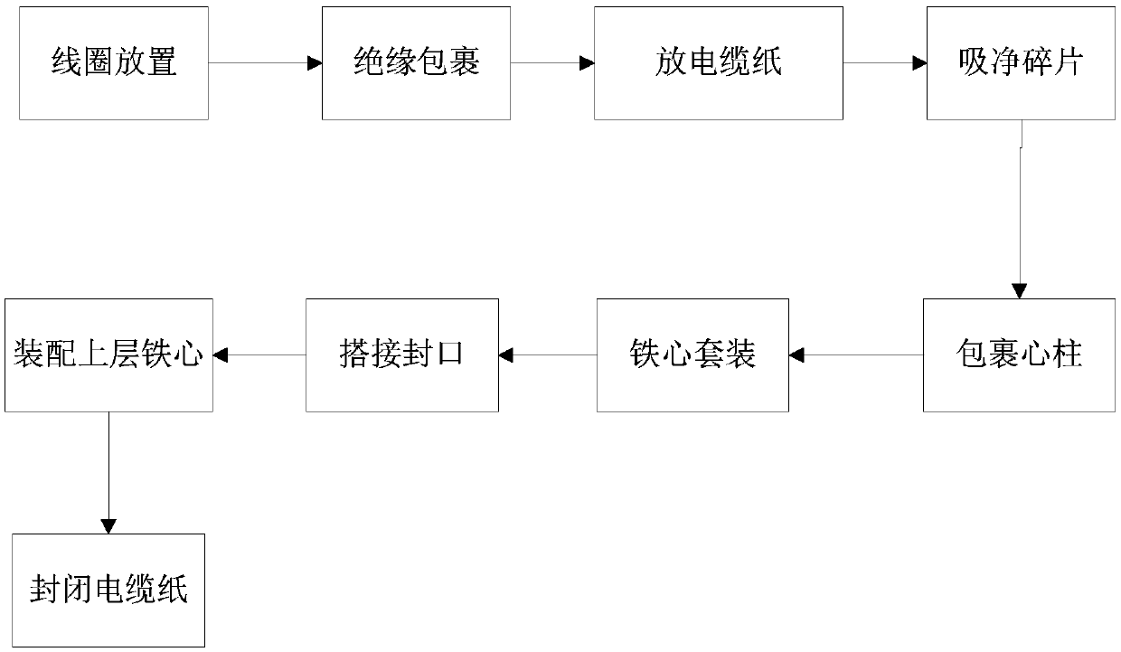
[0043] Such as figure 2 As mentioned above, a protective oil-immersed amorphous transformer core assembly method disclosed in the embodiment of the present invention includes the following steps:

[0044] (1) The qualified coils on the roller table will be hoisted on the brackets of the assembly table according to the phase sequence;

[0045] (2) Wrap the contact part of the coil with the amorphous core with cable paper;

[0046] (3) Place the upper and lower yoke cable papers of the integral iron core in the inner frame of the coil, and fix the cable papers with adhesive tape along the coil window;

[0047] (4) Hoist the lower layer of amorphous iron cores to the hydraulic flatbed truck in sequence according to the assembly sequence with a special magnetic lifter, and use a vacuum cleaner to clean the amorphous fragments on the iron cores;

[0048] (5) Wrap the part of the amorphous core column with noise-reducing cable paper;

[0049] (6) Open the amorphous core by stack...


PUM


Abstract

The invention discloses an assembling method for a preservative oil immersion type amorphous transformer iron core. Before assembling of the amorphous iron core, the contact portion of the amorphous iron core and a coil is wrapped by cable paper, the column portion of the amorphous iron core is wrapped by noise reduction cable paper; the iron core is sleeved, after the end of an iron core lap joint is sealed, amorphous fragments on the surface are sucked away through a dust collector, glass cement is applied, and the upper and lower surfaces of the iron core are both stuck and covered throughnoise reduction cable paper. Compared with the prior art, the iron core fragment production probability during assembling is lowered, the iron core fragment flowing channel during transformer operation is blocked, and the probability that a short circuit happens due to fragment flowing is lowered, so that the quality of the transformer is ensured, and the service life of the transformer is prolonged.

Description

technical field [0001] The invention belongs to the technical field of power transformer manufacturing, and relates to an assembly method for a protective oil-immersed amorphous transformer core. Background technique [0002] When the amorphous alloy transformer is running, there will be scattered debris on the surface of the iron core. The debris will move to the winding with the circulating oil. When the transformer is running, the debris on the winding will discharge, causing the winding to be short-circuited, seriously affecting the quality of the amorphous transformer. How to effectively protect the oil-immersed amorphous transformer core and reduce the probability of amorphous core fragments is the technical problem to be solved by the present invention. Contents of the invention [0003] Purpose of the invention: Aiming at the problems existing in the prior art, the purpose of the present invention is to provide an assembly method for a protective oil-immersed amorp...

Claims


Application Information

Patent Timeline
IPC IPC(8): H01F41/02
CPCH01F41/0206
Inventor 赵祖祥刘青云
Owner JIANGSU HONGYUAN ELECTRIC
Learn More