

Lane departure early warning method
A technology of deviation warning and road, applied in the direction of signal devices, etc., can solve the problems of not giving, the increase of calculation amount, and the effect of GPS signal validity, so as to reduce the probability of occurrence and ensure the effect of safety.
- Summary
- Abstract
- Description
- Claims
- Application Information
AI Technical Summary
Problems solved by technology
Method used
Image

Examples
Embodiment Construction
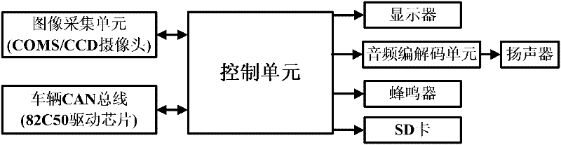
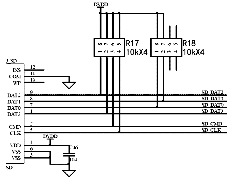
[0020] Such as figure 1 As shown, the road departure warning system adopted in an embodiment of the present invention includes an image acquisition unit, a vehicle CAN bus, a control unit, a display, an audio codec unit, a buzzer, an SD card and a loudspeaker, and the image acquisition unit, the vehicle CAN bus and The control unit is bidirectionally connected, the display, the audio codec unit, the buzzer, the SD card are connected with the control unit, and the audio codec unit is connected with the loudspeaker.
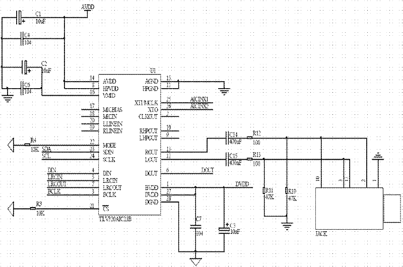
[0021] The CAN bus of the vehicle adopts 82C50 driver chip, the image acquisition unit adopts COMS or CCD camera, the image pixel is not less than 700,000, the viewing angle is not less than 90 degrees, color or black and white, the video frame refresh rate is not less than 25 frames per second, and it is installed in the rear view of the vehicle. At the mirror, the audio codec unit uses the TLV320AIC23 chip.
[0022] The control unit can be ARM series, DSP series...
PUM
 Abstract
Description
Claims
Application Information