A kind of CT equipment and its dedusting method

A technology of equipment and dust removal device, which is applied in the field of CT equipment and its dust removal, can solve the problems that are not conducive to the efficient use of equipment, more manpower for disassembly and installation, and insufficient cleaning of equipment, so as to save dust removal time, simplify equipment and reduce maintenance cost effect

Active Publication Date: 2021-06-29
SHANGHAI UNITED IMAGING HEALTHCARE
View PDF12 Cites 0 Cited by
  • Summary
  • Abstract
  • Description
  • Claims
  • Application Information

AI Technical Summary

Problems solved by technology

[0004] 1. There will be high travel expenses for the service engineer on the way to the hospital
At the same time, service engineers also consume time on the road, which is not conducive to the efficient use of equipment
Secondly, during the cleaning operation of the service engineer, the internal hardware components of the device may be injured by the service engineer, and at the same time, the service engineer will inevitably be scratched by the internal hardware of the device
[0005] 2. The process of dismantling and installing equipment requires more manpower
Equipment cleaning is not clean enough, thorough

Method used


Image

  • A kind of CT equipment and its dedusting method
  • A kind of CT equipment and its dedusting method
  • A kind of CT equipment and its dedusting method

Examples


Embodiment Construction

[0035] In order to more clearly illustrate the technical solutions of the embodiments of the present application, the following briefly introduces the drawings that need to be used in the description of the embodiments.

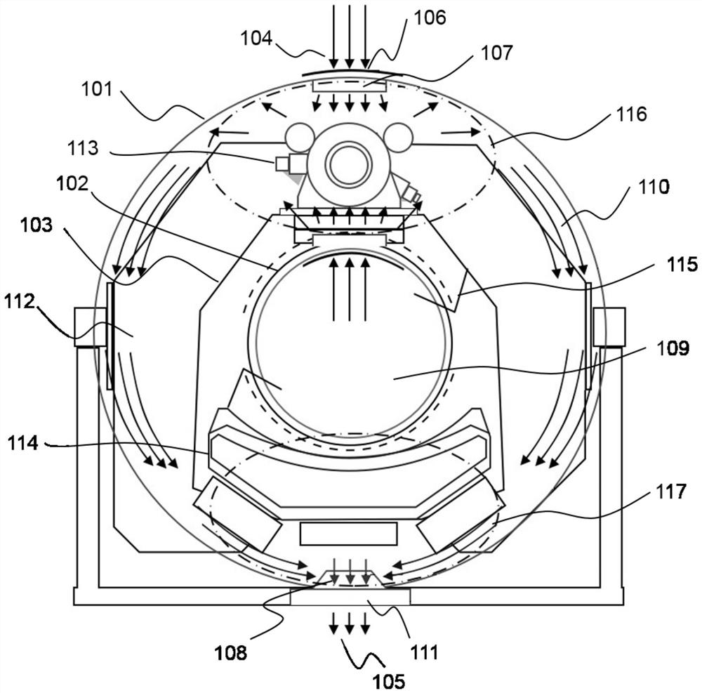
[0036] Such as figure 1 As shown, the CT equipment 100 may include an outer casing 101, an inner casing 102, a rotatable frame 103 and a dust removal device. The dust removal device is arranged on the casing. The dust removal device may include an air inlet 104 , an air outlet 105 , a protective filter 106 , an intake fan 107 and an exhaust fan 108 . The air inlet end 104 and the air outlet end 105 of the dust removal device may be connected through an air duct 110 . The CT apparatus 100 may further include a solid state impurity collector 111 .

[0037] A hollow chamber 112 is formed between the outer casing 101 and the inner casing 102 , and the rotatable frame 103 is disposed inside the hollow chamber 112 . Equipment components are arranged on the rack...


PUM


Abstract

The invention discloses a CT device and a dust removal method thereof. The device may include: a casing, the casing includes an outer casing and an inner casing; a rotatable frame, arranged between the outer casing and the inner casing ; The dust removal device located on the housing; the dust removal device includes an intake fan and an exhaust fan, the intake fan is located at a position other than the bottom of the outer housing, and the exhaust fan is located at the outer housing bottom. The device can clean the inside of the device without disassembling the casing, which can save time and manpower for cleaning the device.

Description

technical field [0001] The application relates to a CT device and a dust removal method thereof. Background technique [0002] Large-scale equipment may involve equipment cleaning issues during use. As the use time increases, the problem of equipment cleaning becomes more and more prominent. Equipment with complex structure and large size is difficult to clean and the cost of cleaning is high. At present, equipment cleaning, such as equipment dust removal, is mainly carried out by service engineers to designated hospitals to use professional service tools to clean equipment. [0003] In some embodiments, current device cleaning methods have the following problems: [0004] 1. The service engineer will incur high travel expenses on the way to the hospital. At the same time, service engineers also consume time on the road, which is not conducive to the efficient use of equipment. Secondly, during the cleaning operation of the service engineer, the internal hardware compon...

Claims


Application Information

Patent Timeline
Patent Type & Authority Patents(China)
IPC IPC(8): A61B6/03
CPCA61B6/035A61B6/4423
Inventor 谭子玉刘洋洋许鑫
Owner SHANGHAI UNITED IMAGING HEALTHCARE
Why Eureka
Try Eureka