Automatic material loading device for tubular element

A technology for automatic feeding and tubular parts, which is applied in metal processing and other directions, and can solve problems such as inability to ensure grasping, complex structure, time-consuming and labor-intensive problems, etc.

Inactive Publication Date: 2018-05-18
嘉善县晓海金属制品厂(普通合伙)
View PDF5 Cites 13 Cited by
  • Summary
  • Abstract
  • Description
  • Claims
  • Application Information

AI Technical Summary

Problems solved by technology

When it is necessary to feed the tubular parts one by one for processing, such as feeding the materials to the shearing table for cutting operations, feeding the materials to the punching table for drilling operations, the traditional method requires manual feeding of the tubular parts one by one, which is time-consuming and laborious , and there are certain security risks
On the market, there are also automatic feeding machines that use manipulators to grab the tubular parts one by one and then feed them. However, this kind of equipment is usually complex in structure, expensive in equipment, high in the precision required by the manipulator, and cannot ensure that only the pipes are grabbed each time. A tubular piece, seriously affecting normal processing operations

Method used


Image

  • Automatic material loading device for tubular element
  • Automatic material loading device for tubular element
  • Automatic material loading device for tubular element

Examples


Embodiment Construction

[0023] In order to make the technical means, creative features, goals and effects achieved by the present invention easy to understand, the present invention will be further described below in conjunction with specific embodiments.

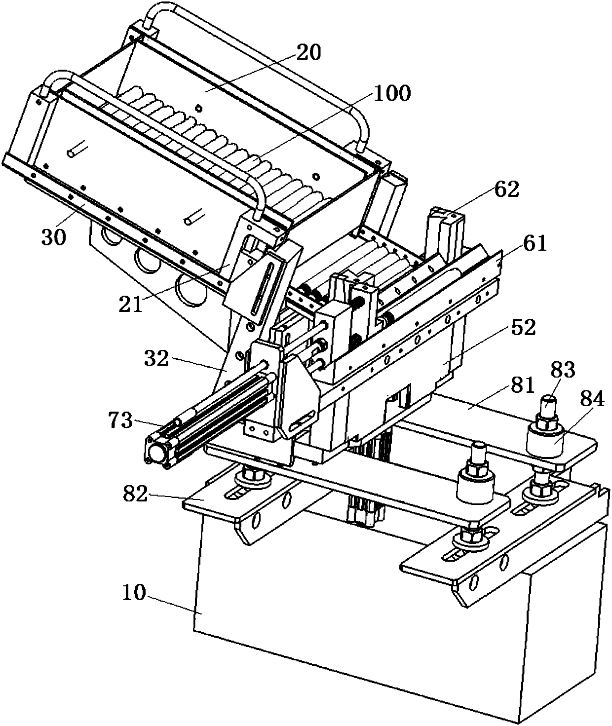
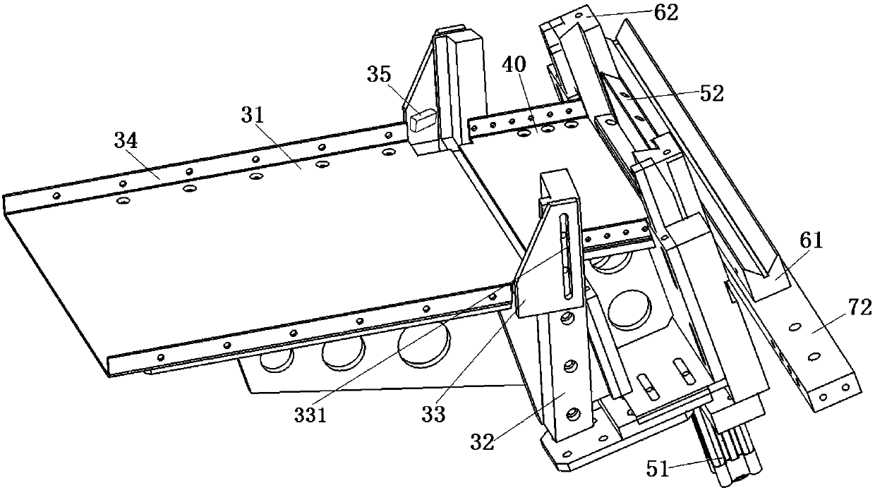
[0024] see Figure 1 to Figure 5 , an automatic feeding device for a tubular member 100 according to the present invention includes a workbench 10 and a feeding mechanism, a material shifting mechanism and a material discharging mechanism arranged on the workbench 10 in sequence from back to front.

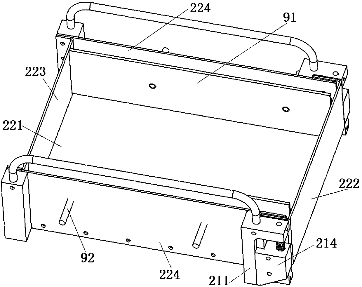
[0025] The feeding mechanism includes a storage box 20 , an opening assembly 21 and a shelf 30 . The material storage box 20 is a rectangular structure with an open top and a cavity inside. The material storage box 20 includes a material storage bottom plate 221 , a front box plate 222 , a rear box plate 223 and two side box plates 224 fixedly connected with the material storage bottom plate 221 . There are two opening assemblies 21, and the opening...


PUM


Abstract

The invention discloses an automatic material loading device for a tubular element. A material storage box comprises a material storage bottom plate, a front box plate, a rear box plate and side box plates; the perforation of a lifting block is sheathed to a guide rod to vertically slide; an elastic spring is sheathed to the guide rod; two ends of the front box plate are independently inserted ininsertion slots on two sides; two lifting blocks are independently fixedly connected with two ends of the front box plate; the material storage box is put on an object placement bottom plate; a material leading plate is arranged between a material supply mechanism and a material movement mechanism; the material movement mechanism comprises a lifting plate capable of vertically moving; the top surface of the lifting plate is an inclination surface which inclines to one side of a discharging mechanism; the discharging mechanism comprises an installation column and a discharging seat with a V-shaped groove; the top surface of the discharging seat is higher than the lower end of a material leading plate; a material pushing rod is also arranged in the V-shaped groove. The automatic material loading device for the tubular element has a compact structure, the tubular element of the box can be sent out in sequence to be cooperated with a subsequent processing operation, feeding accuracy is greatly improved, and the labor intensity of workers is lowered.

Description

technical field [0001] The invention relates to the field of mechanical equipment, in particular to an automatic feeding device for tubular parts. Background technique [0002] In the process of mechanical production and processing, it is often necessary to process and feed tubular parts. Tubular pieces are usually stored in stacks, or in boxes. When it is necessary to feed the tubular parts one by one for processing, such as feeding the materials to the shearing table for cutting operations, feeding the materials to the punching table for drilling operations, the traditional method requires manual feeding of the tubular parts one by one, which is time-consuming and laborious , and there are certain security risks. On the market, there are also automatic feeding machines that use manipulators to grab the tubular parts one by one and then feed them. However, this kind of equipment is usually complex in structure, expensive in equipment, high in the precision required by the...

Claims


Application Information

Patent Timeline
Patent Type & Authority Applications(China)
IPC IPC(8): B23Q7/00B23Q7/10
CPCB23Q7/00B23Q7/10
Inventor 朱建新
Owner 嘉善县晓海金属制品厂(普通合伙)
Why Eureka
Try Eureka