Reducing agent dosing system for injecting a reducing agent into the exhaust-gas flow of an internal combustion engine

A technology of reducing agent and exhaust gas flow, applied in the direction of internal combustion piston engine, combustion engine, mechanical equipment, etc., can solve problems such as discontinuous loading

Active Publication Date: 2013-03-13
VOLVO LASTVAGNAR AB
View PDF5 Cites 4 Cited by
  • Summary
  • Abstract
  • Description
  • Claims
  • Application Information

AI Technical Summary

Problems solved by technology

[0005] Another disadvantage is that the pump pulses of a diaphragm pump or piston pump produce discontinuous loading of the spray nozzles with reducing agent
This effect can already lead to nozzle overloading at small delivery volumes

Method used


Image

  • Reducing agent dosing system for injecting a reducing agent into the exhaust-gas flow of an internal combustion engine

Examples


Embodiment Construction

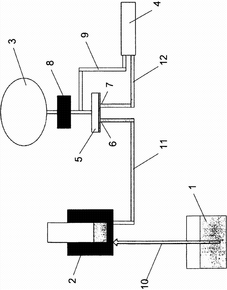
[0031] figure 1 shows a schematic diagram of a reducing agent dosing system according to the invention for injecting reducing agent into the exhaust gas flow of an internal combustion engine for selective catalytic reduction. For this purpose, a reducing agent, such as, for example, a urea solution, in particular according to DIN 70070, is delivered from a tank 1 and delivered by means of a delivery pump 2 . In transfer pump 2 in figure 1 The exemplary embodiment shown is a piston pump.

[0032] With each stroke of the piston pump 2 , the reducing agent is removed from the tank 1 via the suction line 10 and then passed on to the spray nozzle 4 via the pressure line 11 .

[0033] The spray nozzle 4 is a two-substance nozzle in which the reducing agent is atomized by means of compressed air. The aerosol formation is thus achieved outside the nozzle body. But the present invention is not limited to this.

[0034] A compressed air system 3 is provided for supplying the compre...


PUM


Abstract

The invention relates to a reducing agent dosing system for injecting a reducing agent into the exhaust-gas flow of an internal combustion engine for selective catalytic reduction, wherein the dosing system can be or is connected to a reducing agent tank (1) from which reducing agent is extracted and delivered by means of a reducing agent pump (2), wherein there is a compressed air supply (3) and at least one nozzle (4) is provided which is connected to the pressure line (11) of the reducing agent pump (2) and via which the reducing agent is introduced into the exhaust-gas flow and atomized by means of compressed air, wherein the pressure line (11) of the reducing agent pump (2) issues via an inlet (6) into a valve (5) which, when it is subjected to pressure by reducing agent delivered by the reducing agent pump (2), opens up the inlet (6) to the valve (5); and an overflow duct to an outlet (7) of the valve to a dosing line (12) to the nozzle (4).

Description

technical field [0001] The invention relates to a reducing agent dosing system for injecting reducing agent into the exhaust gas flow of an internal combustion engine for selective catalytic reduction, wherein the dosing system can be connected / connected to a reducing agent tank and taken out from the reducing agent tank And the reducing agent is conveyed by means of a reducing agent pump, wherein there is a compressed air supply and at least one nozzle is provided, which nozzle is connected to the pressure line of the reducing agent pump and through which the reducing agent is introduced into the exhaust gas flow and by means of compressed air be atomized. Background technique [0002] Catalysts for selective catalytic reduction, so-called SCR catalysts (English: selective catalytic reduction, abbreviation: SCR), are used in order to reduce nitrogen oxide emissions from diesel engines, combustion plants, waste combustion plants, industrial plants, etc. For this purpose, re...

Claims


Application Information

Patent Timeline
Patent Type & Authority Applications(China)
IPC IPC(8): F01N3/20
CPCF01N2610/1433F01N2610/08F01N3/2066Y02T10/24F01N2610/14F01N2610/02Y02T10/12Y10T137/85978F01N3/20F01N3/24F01N3/28
Inventor A·卡塞尔W·奥弗霍夫
Owner VOLVO LASTVAGNAR AB
Why Eureka
Try Eureka