High-speed vacuum pipeline train intermediate station departure and transfer system

A technology of vacuum pipelines and intermediate stations, which is applied in tunnel systems, sliding/floating railway systems, roads, etc., and can solve the problems of only starting and ending stations, which cannot be used for high-speed pipeline trains, etc.

Active Publication Date: 2018-05-18
王军
View PDF8 Cites 5 Cited by
  • Summary
  • Abstract
  • Description
  • Claims
  • Application Information

AI Technical Summary

Problems solved by technology

[0002] High-speed vacuum tube trains have become the main direction of transportation development in high-tech countries because of their high-speed, fast, safe, energy-saving and many other advantages. my country has even proposed to take high-speed tube trains with a speed of up to 4000 kilometers per hour as the main research topic of future rail trains. , but most of the current studies are through trains, only the starting point and the terminal station
[0003] It is impossible for any train to have only a starting station and a terminal station, especially between the two cities with a line length of thousands of kilometers, there must be a corresponding station for passengers from all over the place to board and get off. It takes only one to four or five minutes for a distance of several kilometers to thousands of kilometers, and the distance of hundreds of kilometers, and the passing pipeline must be a vacuum, so the current high-speed railway platform and transfer methods cannot be used for high-speed pipeline trains

Method used


Image

  • High-speed vacuum pipeline train intermediate station departure and transfer system
  • High-speed vacuum pipeline train intermediate station departure and transfer system
  • High-speed vacuum pipeline train intermediate station departure and transfer system

Examples


Embodiment Construction

[0038] The present invention will be further described below in conjunction with the drawings.

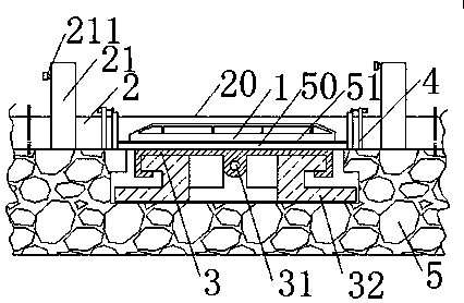
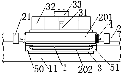
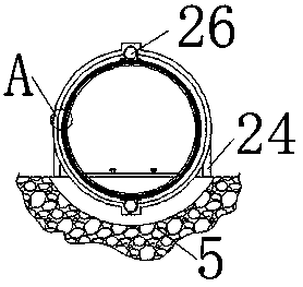
[0039] Such as Figure 1-9 As shown in the figure, a high-speed vacuum pipeline train intermediate station departure and transfer system includes train 1 line, the bottom of the train 1 line is provided with a roadbed 5, the roadbed 5 is provided with a fixed vacuum pipeline 2, the fixed vacuum A fixed track base plate is provided in the pipeline 2, a fixed track is provided on the fixed track base plate, a plurality of transfer sections are set on the train line, and correspondingly set slide guide rails 32 are provided in the subgrade 5 corresponding to the transfer section , The sliding table guide rail 32 is provided with a sliding table surface 3 that can move horizontally along the sliding table guide rail 32 perpendicular to the train line, and the sliding table surface 3 is provided with two sets of the same specifications that can move horizontally with the sliding table surf...


PUM

PropertyMeasurementUnit
Thicknessaaaaaaaaaa

Abstract

The invention belongs to the technical field of high-speed vacuum pipeline trains, and particularly relates to a high-speed vacuum pipeline train intermediate station departure and transfer system. The high-speed vacuum pipeline train intermediate station departure and transfer system comprises a train route, the train route is provided with a fixed vacuum pipeline, a fixed rail base plate is arranged in the vacuum pipeline, a fixed rail is arranged on the fixed rail base plate, and a plurality of transfer ranges are arranged on the train route; a sliding table guide rail is arranged in a roadbed corresponding to each transfer range, a sliding table mesa is arranged on each sliding table guide rail, and movable vacuum pipelines are arranged on the sliding table mesas; and movable rail baseplates are arranged in the movable vacuum pipelines, movable rails are arranged on the movable rail base plates, and the movable vacuum pipelines can horizontally move through the sliding table mesasto be connected with the fixed vacuum pipelines in a butt joint mode. According to the high-speed vacuum pipeline train intermediate station departure and transfer system, the sliding table mesas capable of horizontally moving are arranged in the transfer ranges, through cooperation of the standby movable vacuum pipelines and the transfer movable vacuum pipelines, rail transfer of a vacuum pipeline route is achieved within a short time, and further the purposes of parking and departure and transfer of a train at an intermediate station in the running process are achieved.

Description

Technical field [0001] The invention belongs to the technical field of high-speed vacuum tube trains, and specifically relates to a departure and transfer system for a high-speed vacuum tube train intermediate station. Background technique [0002] High-speed vacuum pipeline trains have become the main direction of transportation development in high-tech countries because of their high speed, safety, energy saving and many other advantages. my country has even proposed to take high-speed pipeline trains with a speed of up to 4000 kilometers per hour as the main research topic of future rail trains. , But most of the current researches are through trains, with only the starting point and the terminal station. [0003] It is impossible for any train to have only a departure station and a terminal station. In particular, there must be corresponding stations in the middle of the two cities with a line of thousands of kilometers for passengers from all over the country to board and disem...

Claims


Application Information

Patent Timeline
IPC IPC(8): B61B13/08B61B13/10
CPCB61B13/08B61B13/10
Inventor 王军
Owner 王军
Why Eureka
Try Eureka