Powder rotating detonation space engine

An engine and powder technology, which is applied in the field of powder rotary detonation space engines, can solve the problems of increasing the weight and design difficulty of the propulsion system, long-term storage and leakage of high-pressure gas, low specific impulse and storage density, etc., and achieves long-term storage. Application value, small size effect

Pending Publication Date: 2022-01-04
PLA PEOPLES LIBERATION ARMY OF CHINA STRATEGIC SUPPORT FORCE AEROSPACE ENG UNIV
View PDF0 Cites 0 Cited by
  • Summary
  • Abstract
  • Description
  • Claims
  • Application Information

AI Technical Summary

Problems solved by technology

Chemical propulsion systems can achieve rapid thrust response, but long-term storage of high-pressure gases in various chemical propulsion systems may cause leakage risks, and some propellants are toxic or even corrosive, making it difficult to store for a long time, and the specific impulse and storage density are not high
Even if the storage density can be increased by increasing the pressure, when the pressure rises to a certain level, the gas no longer satisfies the ideal gas state equation. When the pressurization continues, although the pressure rises sharply, the mass increment of the gas is small
In addition, for example, the new non-toxic and pollution-free hydroxylamine nitrate (HAN) and ammonium dinitramide (ADN) monopropellants also need to overcome the need for special configuration injectors, modular partitioned catalytic beds, long life and durability. Key technologies such as high-temperature catalysts and high-decomposition active propellants greatly increase the weight and design difficulty of the propulsion system

Method used


Image

  • Powder rotating detonation space engine
  • Powder rotating detonation space engine
  • Powder rotating detonation space engine

Examples


Embodiment Construction

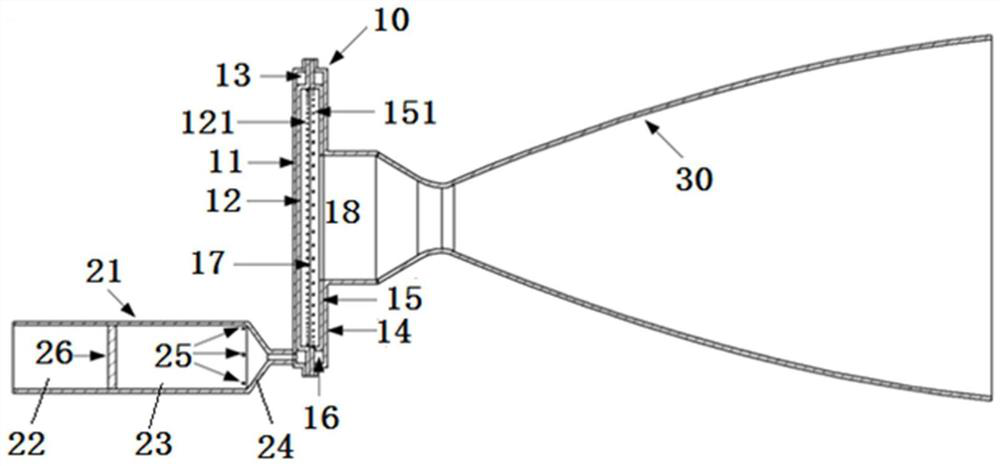
[0038] The present invention will be further described in detail below in conjunction with the accompanying drawings and specific preferred embodiments.

[0039] In the description of the present invention, it should be understood that the orientations or positional relationships indicated by the terms "left side", "right side", "upper", "lower" are based on the orientations or positional relationships shown in the accompanying drawings, and are only For the purpose of describing the present invention and simplifying the description, rather than indicating or implying that the device or element referred to must have a specific orientation, be constructed and operate in a specific orientation, "first", "second" and the like do not represent components importance, and therefore should not be construed as limiting the invention. The specific dimensions used in this embodiment are only for illustrating the technical solution, and do not limit the protection scope of the present in...


PUM


Abstract

The invention discloses a powder rotating detonation space engine. The powder rotating detonation space engine comprises a rotating detonation combustion chamber, a spray pipe, a powder fuel supply device, an oxidizing agent supply device and an ignition device; the rotating detonation combustion chamber comprises a left disc outer shell, a left disc inner shell, a right disc inner shell and a right disc outer shell which are sequentially and coaxially arranged from left to right; a sealed disc-shaped combustion cavity is formed between the left disc inner shell and the right disc inner shell; a fuel premixing cavity is formed between the left disc outer shell and a left disc; an oxidizing agent premixing cavity is formed between the right disc outer shell and the right disc inner shell; the powder fuel supply device comprises a plurality of powder storage tanks and a supercharging device; and each powder storage tank can be used for adding micron-sized powder fuel into the fuel premixing cavity under the supercharging action of the supercharging device. According to the powder rotating detonation space engine, micron-scale powder fuel detonation combustion is adopted for achieving propulsion, the powder rotating detonation space engine can adapt to severe external environments, and the axial size of the detonation combustion chamber can be greatly reduced so that the powder rotating detonation space engine can adapt to installation of spacecrafts, such as satellites and the like.

Description

technical field [0001] The invention relates to the field of rotary detonation, in particular to a powder rotary detonation space engine. Background technique [0002] The role of the spacecraft's chemical propulsion system is to burn and release chemical energy, which is then converted into exhaust kinetic energy to provide thrust for the spacecraft. The liquid chemical fuels widely used in spacecraft include liquid ammonia, butane, anhydrous hydrazine, nitric acid, and DT-3 mixed with hydrazine and water, etc. These gaseous liquid fuels are mainly stored in the form of high-pressure gas or low-pressure liquid. The stable fuel supply and combustion heat release can be realized through the supply device. Chemical propulsion systems can achieve rapid thrust response, but long-term storage of high-pressure gases in various chemical propulsion systems may cause leakage risks. Some propellants are toxic or even corrosive, making it difficult to store for a long time, and the sp...

Claims


Application Information

Patent Timeline
Patent Type & Authority Applications(China)
IPC IPC(8): F02C5/02F02C3/26F02K7/02F23R3/56
CPCF02C5/02F02C3/26F02K7/02F23R3/56
Inventor 林伟舒晨智悦晏成龙聂万胜苏凌宇陈朋王鹏罗修棋
Owner PLA PEOPLES LIBERATION ARMY OF CHINA STRATEGIC SUPPORT FORCE AEROSPACE ENG UNIV
Why Eureka
Try Eureka