Control system for automatic transmission

a control system and automatic transmission technology, applied in the direction of mechanical control devices, process and machine control, instruments, etc., can solve the problems of increasing production costs, unable to reverse inhibit control, and increasing device size and weight, so as to increase production costs and increase the size and weight of the device

Active Publication Date: 2012-10-16
AISIN AW CO LTD
View PDF9 Cites 2 Cited by
  • Summary
  • Abstract
  • Description
  • Claims
  • Application Information

AI Technical Summary

Benefits of technology

[0005]However, providing the cut-off valve as described above in order to perform a reverse inhibit control may increase the size and weight of the device, as well as raise production costs. If the reverse inhibit control is performed on the basis of output signals from a position sensor that detects the shift range, the reverse inhibit control may not be performed in the event of a failure of the position sensor.
[0006]Hence, the present invention realizes a control system for an automatic transmission having a structure that does not use a cut-off valve, and which can perform a reverse inhibit control even if a detection unit that detects a shift range selected by a shift selection unit fails.
[0007]According to a first aspect of the present invention, an avoidance unit is provided for shifting to a forward shift speed that does not engage the first friction engagement element, which engages in predetermined forward and reverse speeds, if a failure judgment unit judges that the detection unit has failed. Therefore, the reverse shift speed is not formed even if the detection unit has failed and cannot detect the shift range selected using the shift selection unit, and the reverse shift speed is selected in error during forward travel. In other words, in the event of a detection unit failure, the first solenoid valve that supplies and discharges an engagement pressure to the hydraulic servo of the first friction engagement element cannot regulate the pressure in accordance with the shift range selected using the shift selection unit. Therefore, if the reverse range is selected in error while the first friction engagement element is engaged during forward travel, the reverse shift speed may be formed. However, by shifting to a forward shift speed that does not engage (that releases) the first friction engagement element when the detection unit has failed as in the present invention, formation of the reverse shift speed can be suppressed even if the detection unit has failed and the reverse range is selected in error during forward travel. Thus, the reverse inhibit control can be executed even if the detection unit has failed. In addition, since there is no need to provide a cut-off valve, a smaller, lighter, and less expensive device can be achieved.
[0008]According to a second aspect of the present invention, the second friction engagement element that forms the reverse shift speed is engaged by the reverse range pressure supplied through the manual shift valve. Therefore, if the reverse shift range is selected in error during a failure of the detection unit, the second friction engagement element is engaged based on the shift range. Accordingly, by using a forward shift speed that does not engage the first friction engagement element, formation of the reverse shift speed can be reliably suppressed even if the reverse shift range is selected in error and the second friction engagement element is engaged.
[0009]According to a third aspect of the present invention, upshifting is performed to shift from the predetermined forward shift speed to a forward shift speed that does not engage the first friction engagement element. Therefore, it is possible to suppress a sudden increase in the engine speed that may cause over-revving, and operation of the engine brake that may cause a sudden change in the driving force.

Problems solved by technology

However, providing the cut-off valve as described above in order to perform a reverse inhibit control may increase the size and weight of the device, as well as raise production costs.
If the reverse inhibit control is performed on the basis of output signals from a position sensor that detects the shift range, the reverse inhibit control may not be performed in the event of a failure of the position sensor.
Therefore, the reverse shift speed is not formed even if the detection unit has failed and cannot detect the shift range selected using the shift selection unit, and the reverse shift speed is selected in error during forward travel.

Method used


Image

  • Control system for automatic transmission
  • Control system for automatic transmission
  • Control system for automatic transmission

Examples


Embodiment Construction

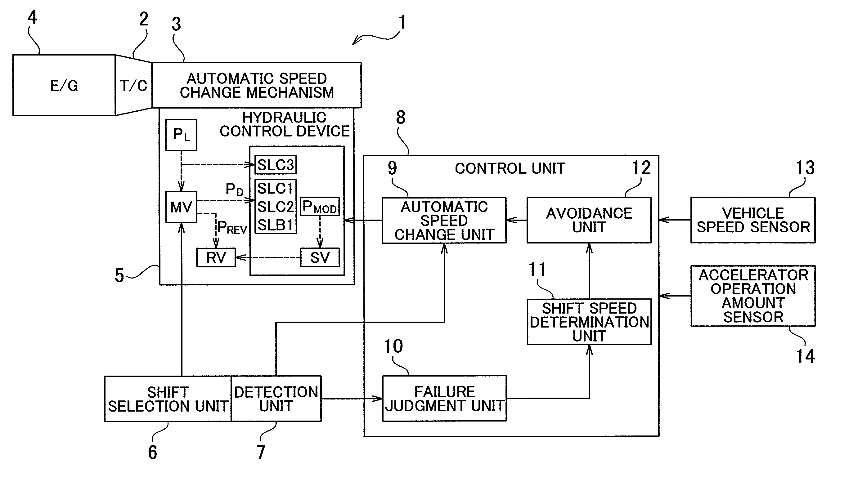
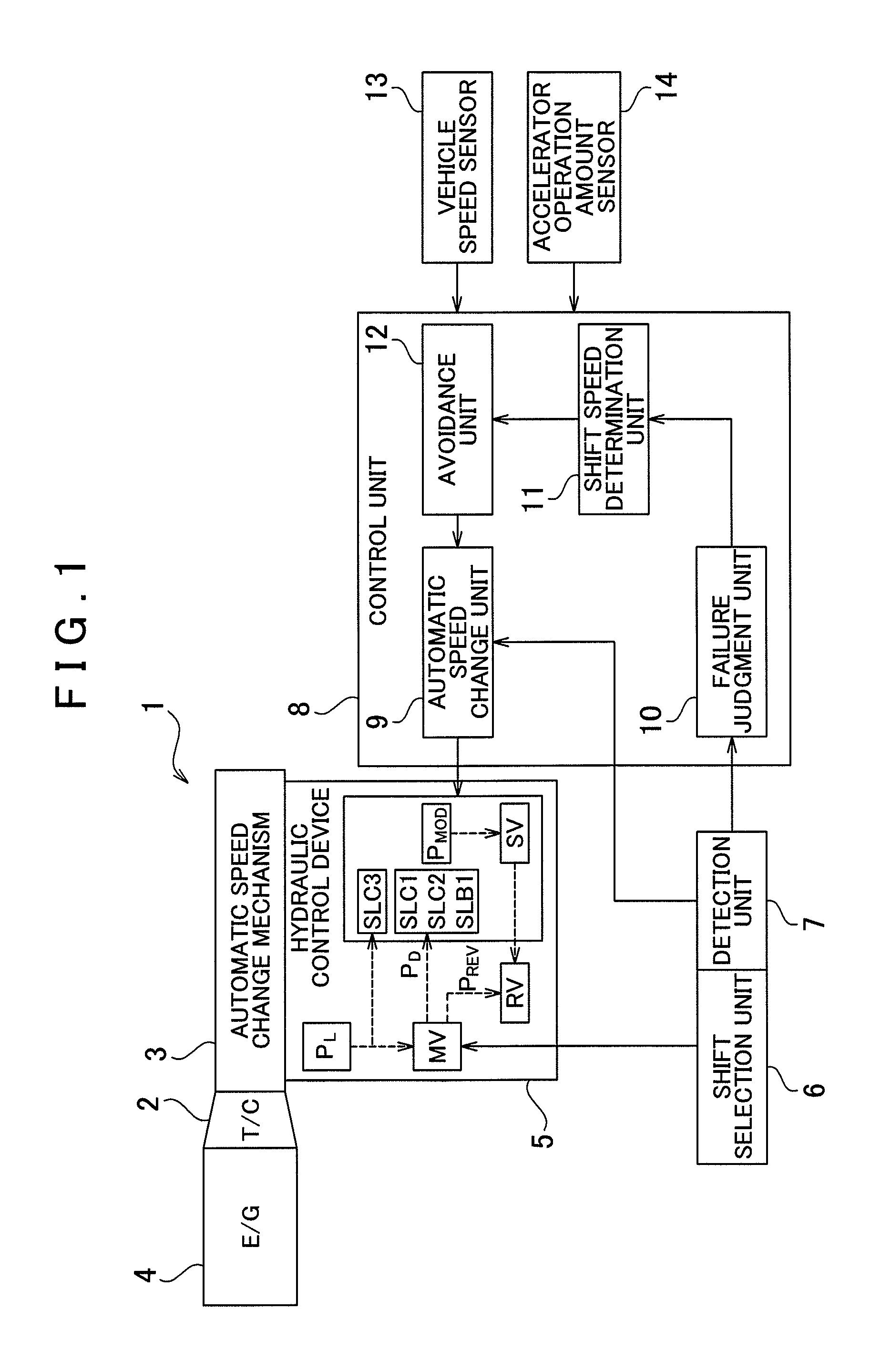
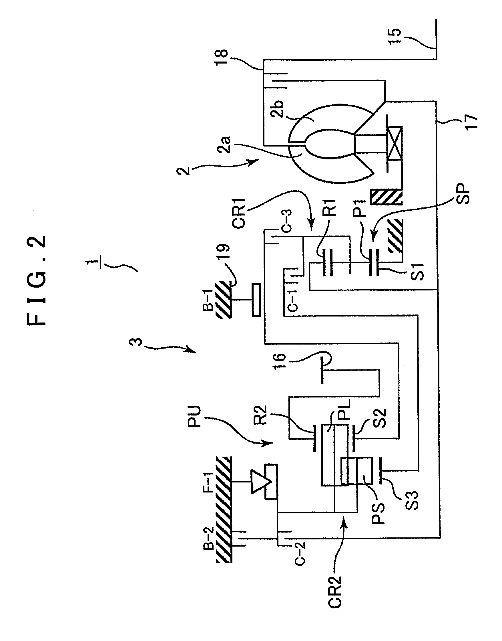
[0018]An embodiment of the present invention will be described below with reference to FIGS. 1 to 7. A brief overview of an automatic transmission and a control system therefor according to the present embodiment will be given based on FIGS. 1 and 2. As illustrated in FIG. 1, an automatic transmission 1 is well suited for use in an FF type (front engine, front wheel drive) vehicle, and is structured capable of achieving six forward speeds and one reverse speed. The automatic transmission 1 has a torque converter 2 and an automatic speed change mechanism 3. Torque from an engine (drive source) 4 is transmitted to the automatic speed change mechanism 3 through the torque converter 2. A control system for this automatic transmission includes a hydraulic control device 5 and a control unit (ECU) 8, in addition to the automatic speed change mechanism 3. The control system drives on the basis of signals from a detection unit 7 that detects a shift range selected by a shift selection unit ...


PUM


Abstract

A control system for an automatic transmission that does not require a cut-off valve, and that can inhibit a reverse control even if a detection unit for detecting a shift range fails. The control system includes a first friction engagement element, which is engaged in predetermined forward and reverse shift speeds, a detection unit that detects a shift range from shift ranges that include a forward range and a reverse range; a failure judgment unit for judging failure of the detection unit, and an avoidance unit for shifting to a forward shift speed that does not engage the first friction engagement element if the failure judgment unit determines that the detection unit has failed.

Description

INCORPORATION BY REFERENCE[0001]The disclosure of Japanese Patent Application No. 2009-142481 filed on Jun. 15, 2009 including the specification, drawings and abstract is incorporated herein by reference in its entirety.BACKGROUND OF THE INVENTION[0002]The present invention relates to a control system for an automatic transmission mounted in a vehicle or the like. More specifically, the present invention relates to a so-called reverse inhibit control in which a reverse shift speed is not formed when the reverse shift speed is selected in error during forward travel.DESCRIPTION OF THE RELATED ART[0003]In a multi-speed automatic transmission mounted in a vehicle or the like, a plurality of (e.g. two) friction engagement elements (clutches and brakes) is hydraulically controlled to engage depending on the shift speed in order to form a transmission path of a speed change gear mechanism. In such an automatic transmission, conventionally, if a reverse range is selected in error during fo...

Claims


Application Information

Patent Timeline
Patent Type & Authority Patents(United States)
IPC IPC(8): F16H61/18F16H59/08F16H59/44F16H61/12F16H61/16
CPCF16H61/12F16H59/105F16H2061/1208Y10T477/6935F16H2061/1284Y10T74/20091F16H2061/122
Inventor NISHIDE, MASAKIMURAKAMI, SHINICHIROUMENAKA, KEISUKE
Owner AISIN AW CO LTD
Why Eureka
Try Eureka