An inflatable hang gliding drone

An inflatable, unmanned aerial vehicle technology, applied in gliders, unmanned aerial vehicles, wings and other directions, can solve the problems of limited storage and transportation space of glider unmanned aerial vehicles, inability to quickly change orbits, etc., to solve the problem of storage and transportation. The effect of space constraints and inability to quickly change orbits, low cost, and good folding performance

Active Publication Date: 2020-07-03
HARBIN INST OF TECH
View PDF8 Cites 0 Cited by
  • Summary
  • Abstract
  • Description
  • Claims
  • Application Information

AI Technical Summary

Problems solved by technology

[0003] The purpose of the present invention is to solve the problem of limited storage and transportation space and inability to quickly change the orbit of the hang gliding UAV, and provides an inflatable hang gliding UAV. The technical solution is as follows:
[0005] The beneficial effects of the present invention are: the inflatable side wings can be quickly inflated and deployed and deflated and retracted during the advancing process of the UAV to realize track change, and can be repeatedly inflated and deployed and deflated and retracted, which solves the storage and transportation space of the gliding wing UAV The problem of being limited and unable to quickly change orbits; the inflatable tube is made of flexible skin material, which is elastic and has a strong ability to absorb collision energy, which can reduce accidental damage during operations such as flight, landing and transportation; the inflatable side wings have ultra-light weight, Unique advantages such as good folding performance and low cost can provide a new technical approach for deployable structures or variant structures in the aerospace field

Method used


Image

  • An inflatable hang gliding drone
  • An inflatable hang gliding drone
  • An inflatable hang gliding drone

Examples


Embodiment Construction

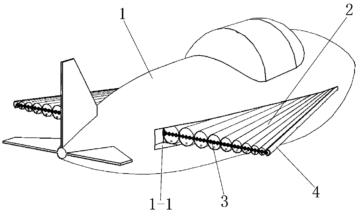
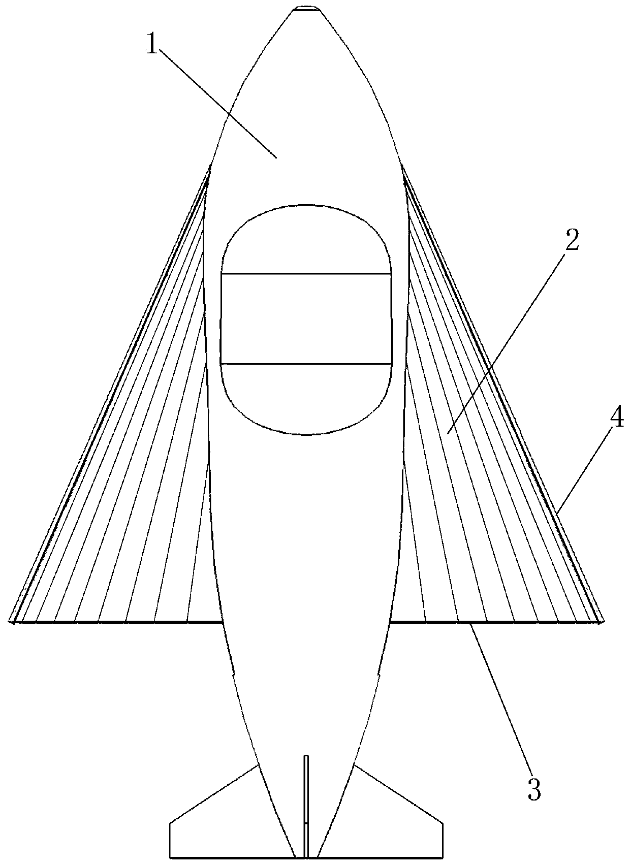
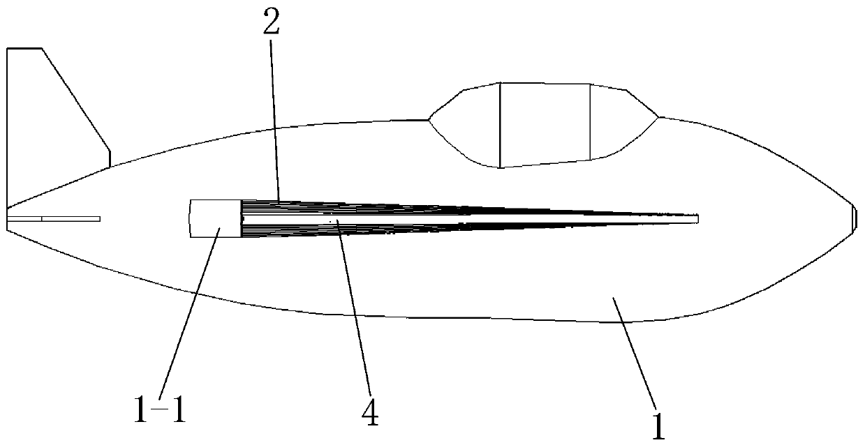
[0011] refer to Figure 1 to Figure 5 , an inflatable glider unmanned aerial vehicle, which comprises a fuselage 1 and inflatable flanks 2 arranged on both sides of the fuselage 1, each inflatable flank 2 is composed of a plurality of variable-section inflatable tubes, and each variable-section The cross-sectional radius of the inflatable tube increases from the front end to the rear end, the front-end cross-sectional radius of all the variable-section inflatable tubes is the same, and the rear-end cross-sectional radius of all the variable-section inflatable tubes of each inflatable flank 2 gradually increases from the outside to the inside. , all the variable-section inflatable tubes of each inflatable side wing 2 are connected in turn and are connected by line, the front end of each inflatable side wing 2 is fixedly connected with the fuselage 1, and an X-shaped telescopic extension is provided on the rear side of each inflatable side wing 2 Mechanism 3, the central axis 3-...


PUM


Abstract

An inflatable hang gliding UAV belongs to the field of UAV technology and solves the problems of limited storage and transportation space and inability to quickly change orbits of the hang gliding UAV. It includes a fuselage and inflatable Each inflatable wing is composed of multiple variable-section inflatable tubes. The cross-sectional radius of each variable-section inflatable tube gradually increases from the front end to the rear end. The front-end cross-sectional radii of all variable-section inflatable tubes are the same. The cross-sectional radius of the rear end of all variable-section inflatable tubes of the inflatable wing gradually increases from the outside to the inside, and all the variable-section inflatable tubes of each inflatable wing are connected in sequence and are connected by lines, and the front end of each inflatable wing is connected to the fuselage Fixed connection, an X-shaped telescopic mechanism is arranged on the rear side of each inflatable wing, and the central axis of each X unit of the X-type telescopic mechanism is fixedly connected with the inflatable wing; There is a rigid windshield; the invention is used for drones.

Description

technical field [0001] The invention belongs to the technical field of unmanned aerial vehicles, and in particular relates to an inflatable glider unmanned aerial vehicle. Background technique [0002] UAVs have obvious advantages such as no risk of casualties. With the rapid development of UAV technology, glider UAVs have been widely used; due to the large area of ​​flank structures, current glider UAVs require large parking spaces space, which is not conducive to storage and transportation; and when the glider UAV encounters natural enemies such as birds and other natural enemies, it cannot quickly change orbits to avoid, and the safety hazard is relatively large; in order to solve the problem of limited storage and transportation space and inability to quickly change orbits, the proposed this program. SUMMARY OF THE INVENTION [0003] The purpose of the present invention is to solve the problem that the storage and transportation space of the glider unmanned aerial veh...

Claims


Application Information

Patent Timeline
Patent Type & Authority Patents(China)
IPC IPC(8): B64C3/30B64C31/02
CPCB64C3/30B64C31/02B64U10/00
Inventor 卫剑征谭惠丰甄铎
Owner HARBIN INST OF TECH
Why Eureka
Try Eureka