

An inflatable glider drone
An inflatable and unmanned aerial vehicle technology, applied in the field of unmanned aerial vehicles, can solve the problems of limited storage and transportation space of hang glider unmanned aerial vehicles, inability to change orbits quickly, and high rigidity of I-shaped ribs, etc., to solve the problem of storage and transportation space Restricted and unable to quickly change orbit, high rigidity, ultra-light weight effect
Active Publication Date: 2020-07-03
HARBIN INST OF TECH
View PDF8 Cites 0 Cited by
- Summary
- Abstract
- Description
- Claims
- Application Information
AI Technical Summary
Problems solved by technology
[0003] The purpose of the present invention is to solve the problem of limited storage and transportation space and inability to quickly change the orbit of the hang gliding UAV, and provides an inflatable hang gliding UAV. The technical solution is as follows:
[0005] The beneficial effects of the present invention are: the inflatable side wings can be quickly inflated and deployed and deflated and retracted during the advancing process of the UAV to realize track change, and can be repeatedly inflated and deployed and deflated and retracted, which solves the storage and transportation space of the gliding wing UAV The problem of limited and inability to quickly change orbits; the inflatable side wings adopt a rigid-flexible combination structure of flexible skin and ribs, and the I-shaped ribs have high rigidity and strong collision energy absorption capacity, which can reduce accidents during operations such as flight, landing and transportation Damage; The inflatable wing has unique advantages such as ultra-light weight, good folding performance, and low cost, which can provide a new technical approach for the expandable structure or variant structure technology in the aerospace field
Method used
View moreImage
Smart ImageViewing Examples

Examples
specific Embodiment 1
[0014] In the first embodiment, the front end of each rib 2-1 is connected to the fuselage 1 in an opening and closing direction through a rotating shaft 4.
specific Embodiment 2
[0015] In the second embodiment, the rear end of each rib 2-1 is rotatably connected with the central shaft 3-1 in the opening and closing direction through a hinge 5.
specific Embodiment 3
[0016] In the third embodiment, the root of the X-shaped telescopic mechanism 3 is rotatably connected with the fuselage 1 in the opening and closing direction through a shaft 4 or a hinge 5.
[0017] Preferably, the flexible skin 2-2 is made of aramid aluminum foil-coated material. Aramid, also known as Kevlar, plays the role of bearing force, and the aluminum foil plays the role of airtightness.
Login to View More PUM
 Abstract
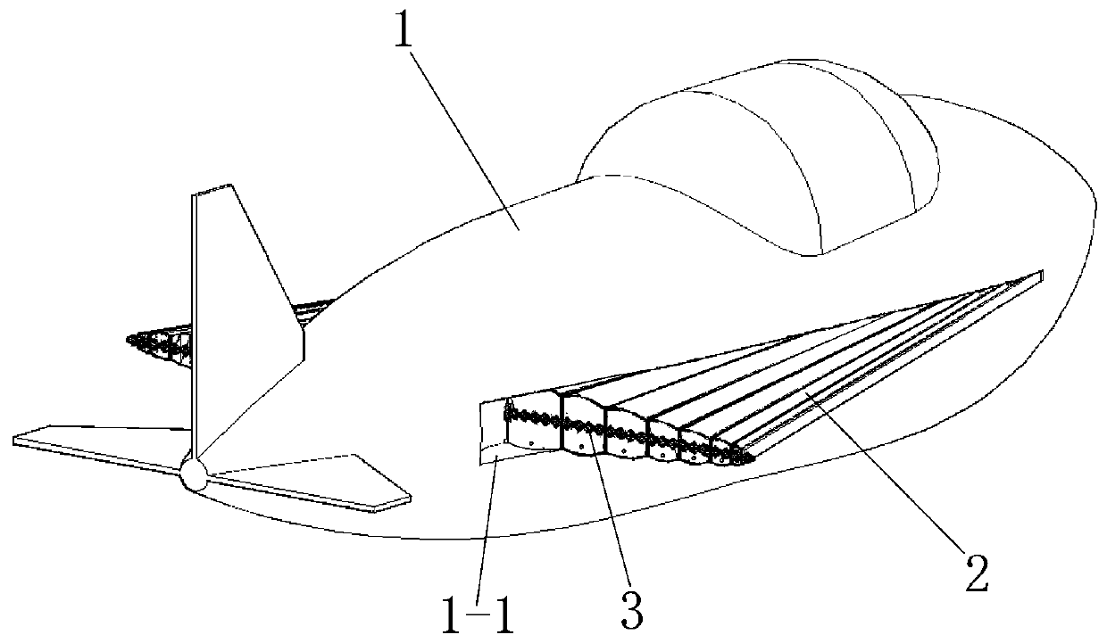
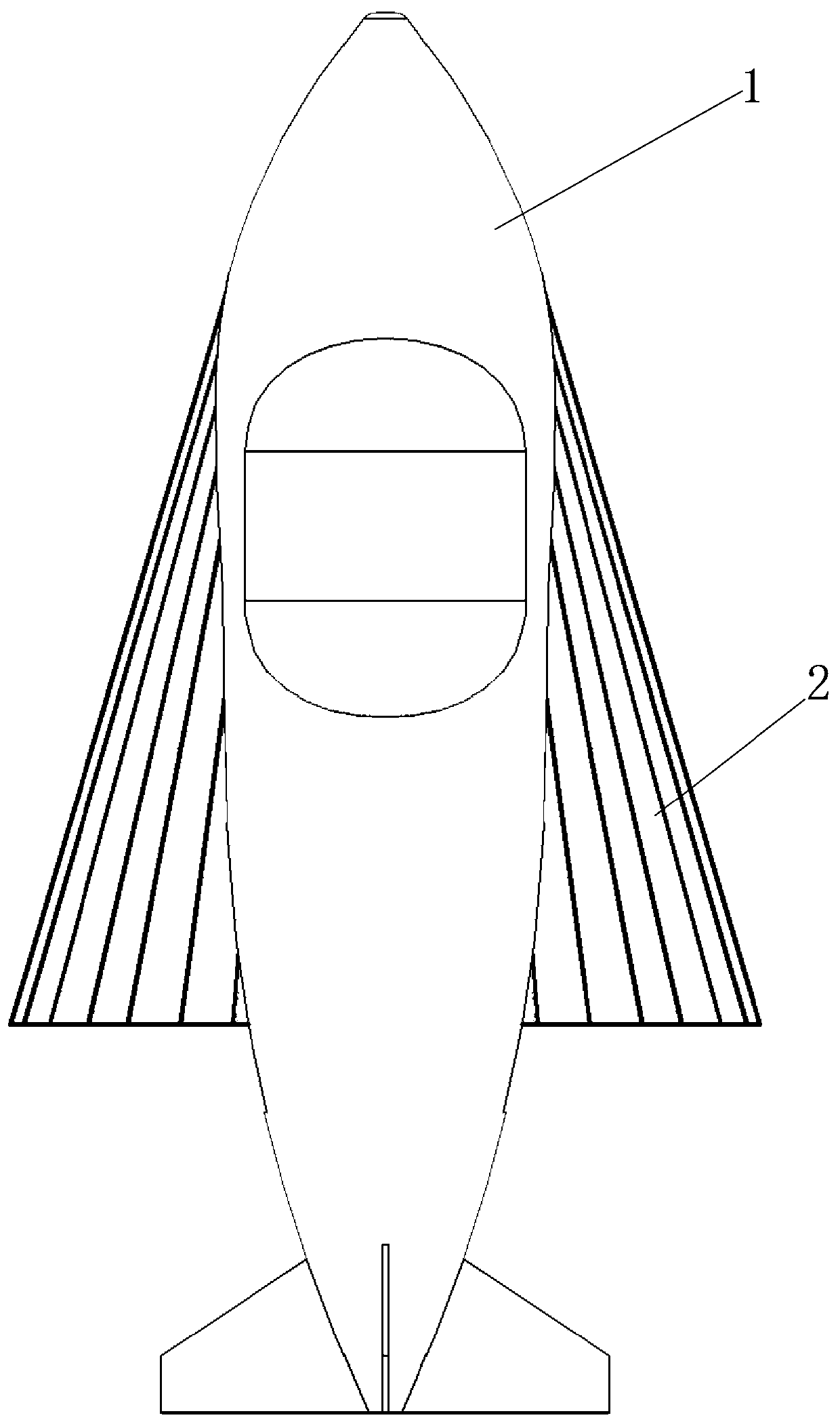
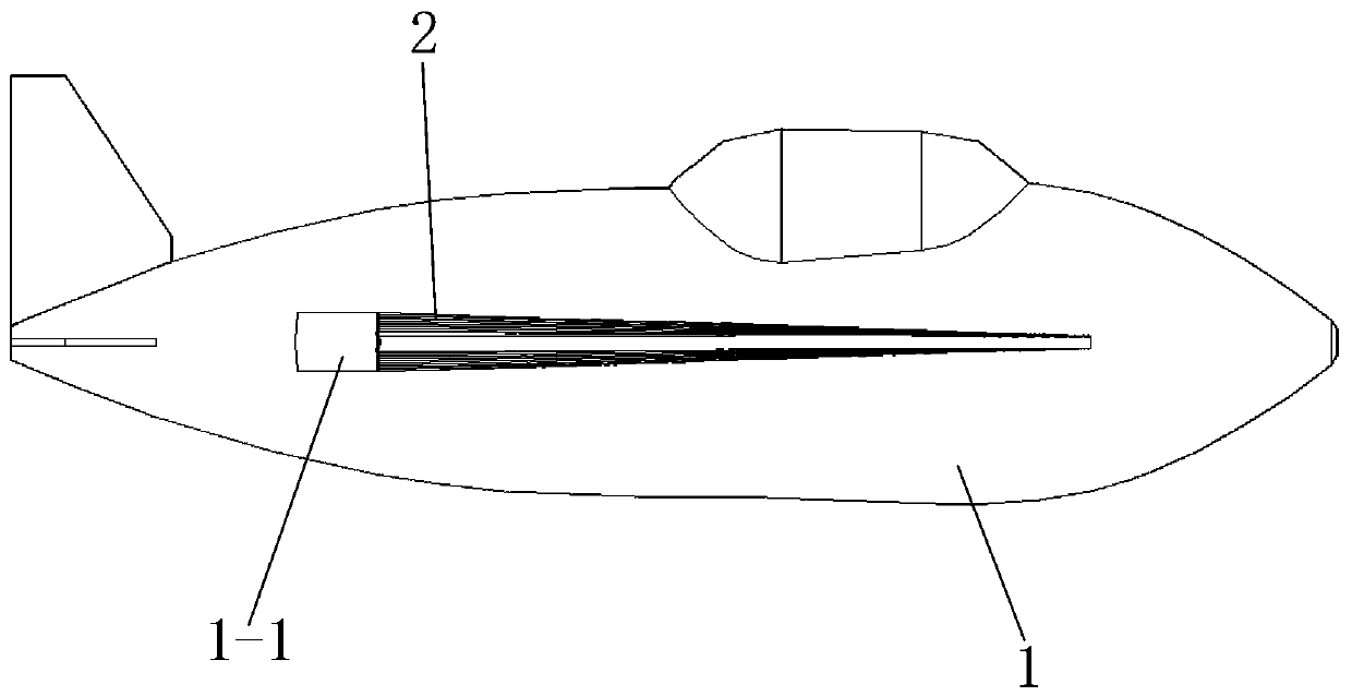
The invention discloses an inflatable hang glider unmanned aerial vehicle and belongs to the technical field of unmanned aerial vehicles. The problem that a hang glider unmanned aerial vehicle has limited storage and transporting space and cannot change track rapidly is solved. The inflatable hang glider unmanned aerial vehicle comprises a fuselage and inflatable side wings arranged on the two sides of the fuselage; each inflatable side wing is composed by sealing connection of a plurality of rib plates arranged in a fan-shaped mode through flexible skins; the flexible skins are bonded with the rib plates; two adjacent rib plates are sealed through the flexible skins on the front, rear, upper and lower surfaces to form gas chambers; the width of each rib plate is gradually increased from the front end to the rear end; the front end widths of all the rib plates are same; the rear end widths of all the rib plates of each inflatable side wing are gradually increased from the outside to the inside; and the rib plates adopt hollow I-shaped plates; air holes are formed in the side walls of the rib plates on the two sides of each gas chamber; the front end of each rib plate is connected with a high-pressure air cylinder and an inflatable control system which are arranged in the fuselage; and exhaust solenoid valves are arranged at the rear ends of the gas chambers. The inflatable hang glider unmanned aerial vehicle is applied to the unmanned aerial vehicles.
Description
Technical field [0001] The invention belongs to the technical field of drones, and specifically relates to an inflatable hang gliding drone. Background technique [0002] UAVs have obvious advantages such as no risk of casualties. With the rapid development of UAV technology, hang gliding UAVs have been widely used; due to the large area of the side wing structure, currently hang gliding UAVs require larger parking Space is not conducive to storage and transportation; and when the hang gliding drone encounters natural enemies such as birds, it cannot quickly change orbit to avoid it, and the potential safety hazard is greater; in order to solve the problem of limited storage and transportation space and the inability to quickly change orbit This program. Summary of the invention [0003] The purpose of the present invention is to solve the problem of limited storage and transportation space for hang gliding wing drones and the inability to quickly change orbit, and to provide a...
Claims
Login to View More Application Information
Patent Timeline
 Patent Type & AuthorityPatents(China)
IPC IPC(8): B64C31/02B64C3/30B64C3/56
CPCB64C3/30B64C3/56B64C31/02
Inventor卫剑征谭惠丰甄铎
OwnerHARBIN INST OF TECH