Synchronization mechanism of unmanned aerial vehicle power rotor wings and unmanned aerial vehicle

A technology of synchronizing mechanism and motor power, which is applied to a transmission device that drives multiple propellers, and a transmission device that is driven by multiple power devices, etc., can solve the problems of poor consistency of multiple engines, and achieve the effect of improving accuracy.

Active Publication Date: 2018-05-18
SHENZHEN QIKER INTELLIGENT TECH CO LTD
View PDF9 Cites 1 Cited by
  • Summary
  • Abstract
  • Description
  • Claims
  • Application Information

AI Technical Summary

Problems solved by technology

[0005] The main purpose of the present invention is to provide a synchronization mechanism for unmanned aerial vehicle power rotors, aiming to solve the problem of poor consistency between multiple engines of existing unmanned aerial vehicles

Method used


Image

  • Synchronization mechanism of unmanned aerial vehicle power rotor wings and unmanned aerial vehicle
  • Synchronization mechanism of unmanned aerial vehicle power rotor wings and unmanned aerial vehicle
  • Synchronization mechanism of unmanned aerial vehicle power rotor wings and unmanned aerial vehicle

Examples


Embodiment Construction

[0027] In order to illustrate the technical solutions of the present invention more clearly, the technical solutions of the various embodiments of the present invention will be described in detail below in conjunction with the accompanying drawings.

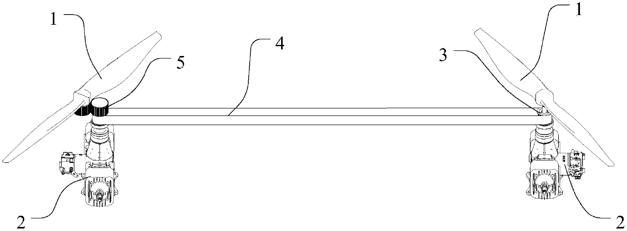
[0028] The present invention proposes a synchronous mechanism for a UAV powered rotor. The UAV includes a fuselage, a control rotor, and two power rotors 1 located on both sides of the fuselage and symmetrical to each other. The motor of the rotor and the two engines 2 driving the power rotor 1,

[0029] like figure 1 As shown, the synchronous mechanism of the UAV power rotor includes synchronous wheels 3 respectively installed on the main shafts of the two engines 2, and a synchronous belt 4 connecting the two synchronous wheels 3.

[0030] In this embodiment, the synchronous wheel 3 is clamped and fixed with the main shaft of the engine 2, so that the two are synchronized, and the synchronous belt 4 is connected with the two s...


PUM


Abstract

The invention discloses a synchronization mechanism of unmanned aerial vehicle power rotor wings. An unmanned aerial vehicle comprises a vehicle body, a control rotor wing, the two power rotor wings located on the two sides of the vehicle body and arranged bilaterally symmetrically, a motor driving the control rotor wing and two engines driving the power rotor wings. The synchronization mechanismof the unmanned aerial vehicle power rotor wings comprises two synchronizing wheels installed on two engine main shafts and a synchronous belt connected with the two synchronizing wheels. Due to the fact that the synchronizing wheels are installed on the engine main shafts and meanwhile the two synchronizing wheels are connected through the synchronous belt, the two synchronizing wheels rotate synchronously, the two engine main shafts rotate synchronously as well, so that the effect that the rotation speeds of the two power rotor wings with power supplied by the two engines are identical is achieved, and the control accuracy of the unmanned aerial vehicle is improved.

Description

technical field [0001] The invention relates to the technical field of unmanned aerial vehicles, in particular to a synchronous mechanism for a powered rotor of an unmanned aerial vehicle and an unmanned aerial vehicle. Background technique [0002] The drones currently used in the civilian market are mainly multi-axis (also known as multi-rotor) drones. Multi-axis UAVs have won widespread favor, thanks to the technical characteristics of multi-axis UAVs that can hover, take off and land vertically, and be easy to control, as well as the low cost advantages of simple structure, easy production and installation, and simple maintenance. Due to the optimization of the endurance and load capacity of UAVs, the more advantageous UAVs in the existing market generally use gasoline-electric hybrid power as the core, that is, use fuel engines to provide lift and forward power, and use electric motors to provide dynamic control. [0003] The number of power rotors driven by fuel engin...

Claims


Application Information

Patent Timeline
Patent Type & Authority Applications(China)
IPC IPC(8): B64D35/06B64D35/08
CPCB64D35/06B64D35/08
Inventor 陈翔斌
Owner SHENZHEN QIKER INTELLIGENT TECH CO LTD
Why Eureka
Try Eureka