An inner support card device for inner support of an annular open member and its application method
A technology for clamping devices and components, applied in auxiliary devices, auxiliary welding equipment, welding equipment, etc., can solve problems such as weak rigidity bearing capacity, self-weight burden, etc., to improve manufacturing accuracy, improve positioning accuracy, ensure accuracy and processing efficiency Effect
- Summary
- Abstract
- Description
- Claims
- Application Information
AI Technical Summary
Problems solved by technology
Method used
Image
Examples
Embodiment 1
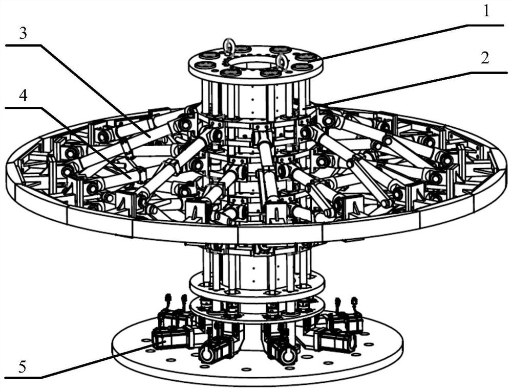
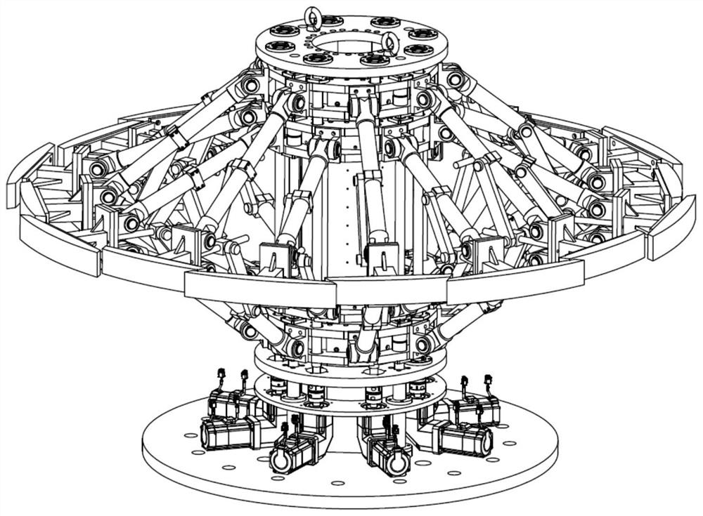
[0038] Embodiment one: if Figure 1 to Figure 10 As shown, the present invention proposes an inner supporting card device supported by an annular open member, including a fixed frame 1, the bottom flange of which is connected to an external mechanism or the ground, and the fixed frame 1 is installed with a center Drive platform 2, convex radial support mechanism 3, concave radial support mechanism 4 and servo drive mechanism 5.
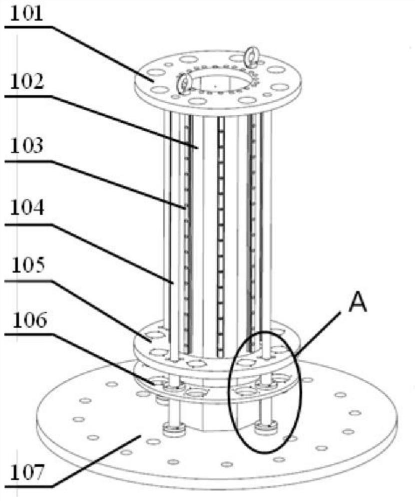
[0039] The fixed frame 1 includes a fixed frame including a bottom plate 107, a top plate 101, a center frame 102 fixed between the bottom plate 107 and the top plate 101, several guide rails 103 arranged on the center frame 102 and vertically arranged, and several guide rails 103 arranged on the bottom plate 107 and the top plate. Between 101 and vertically arranged fixed guide rods 104 , guide rails 103 and fixed guide rods 104 are arranged around the center frame 102 . The center frame 102 is equipped with a bearing seat mounting plate 105 and a r...
Embodiment 2
[0046] Embodiment 2: A method for using the inner supporting card device supported by the annular open member described in Embodiment 1, comprising the following steps:
[0047] a) Penetrate the top of the fixed frame 1 into the ring-shaped open member, and make some convex correction blocks 307 and some concave correction blocks 407 be located at the corresponding positions of the welding seam of the ring-shaped open member;
[0048] b) Drive the center drive assembly B202 and the center drive assembly C203 to move toward each other through the servo motor 506 corresponding to the center drive assembly B202 and the center drive assembly C203, and drive the concave shape correction block 407 to move toward the inner wall of the annular open member through the main support rod B401, and butt against the inner wall of the annular open member; and
[0049] c) Drive the center drive assembly A201 and the center drive assembly D204 to move toward each other through the servo motor ...
PUM
 Abstract
Description
Claims
Application Information
 - R&D
- Intellectual Property
- Life Sciences
- Materials
- Tech Scout
- Unparalleled Data Quality
- Higher Quality Content
- 60% Fewer Hallucinations
Browse by: Latest US Patents, China's latest patents, Technical Efficacy Thesaurus, Application Domain, Technology Topic, Popular Technical Reports.
© 2025 PatSnap. All rights reserved.Legal|Privacy policy|Modern Slavery Act Transparency Statement|Sitemap|About US| Contact US: help@patsnap.com


