Floor projector stand

A projector and pillar technology, applied in the field of projection equipment, can solve problems such as inability to move, inconvenient to carry, and loss of balance, and achieve the effect of preventing inaccurate projection orientation, simple and reasonable design, and meeting the delivery requirements

Active Publication Date: 2018-05-18
黄世仁
View PDF8 Cites 7 Cited by
  • Summary
  • Abstract
  • Description
  • Claims
  • Application Information

AI Technical Summary

Problems solved by technology

[0002] As a conference and teaching tool, projectors are widely used at present. They are usually placed directly on the table or installed on the ceiling of the conference room or classroom through brackets. However, the usual projector brackets are directly installed , cannot be moved, it is only suitable for one type of projector to project in a fixed direction, and it cannot be used if you change another type of projector or want to change the projection direction
With the advancement of science and technology, mobile projection equipment has appeared, that is, a walking shelf is set up, and a projection screen and a projector are set on the shelf at the same time. Although this method does not need to install projection equipment in every classroom or meeting room, but This mobile projection device is bulky, inconvenient to carry, takes up space when moving, easily loses balance, damages the projection device, and has poor practicability

Method used


Image

  • Floor projector stand
  • Floor projector stand
  • Floor projector stand

Examples


Embodiment Construction

[0030] The present invention will be further described in detail below in conjunction with the accompanying drawings and embodiments, so that those skilled in the art can implement it with reference to the description.

[0031] It should be understood that terms such as "having", "comprising" and "including" as used herein do not entail the presence or addition of one or more other elements or combinations thereof. It should be noted that the experimental methods described in the following embodiments, unless otherwise specified, are conventional methods, and the reagents and materials, if not otherwise specified, can be obtained from commercial sources; in the description of the present invention, The terms "transverse", "longitudinal", "axial", "radial", "upper", "lower", "front", "rear", "left", "right", "vertical", "horizontal ", "Top", "Bottom", "Inner", "Outer" and other indicated orientations or positional relationships are based on the orientations or positional relati...


PUM


Abstract

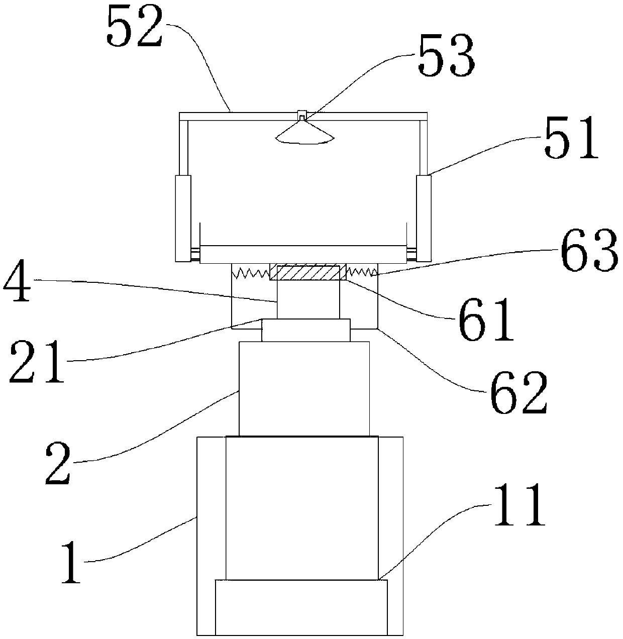
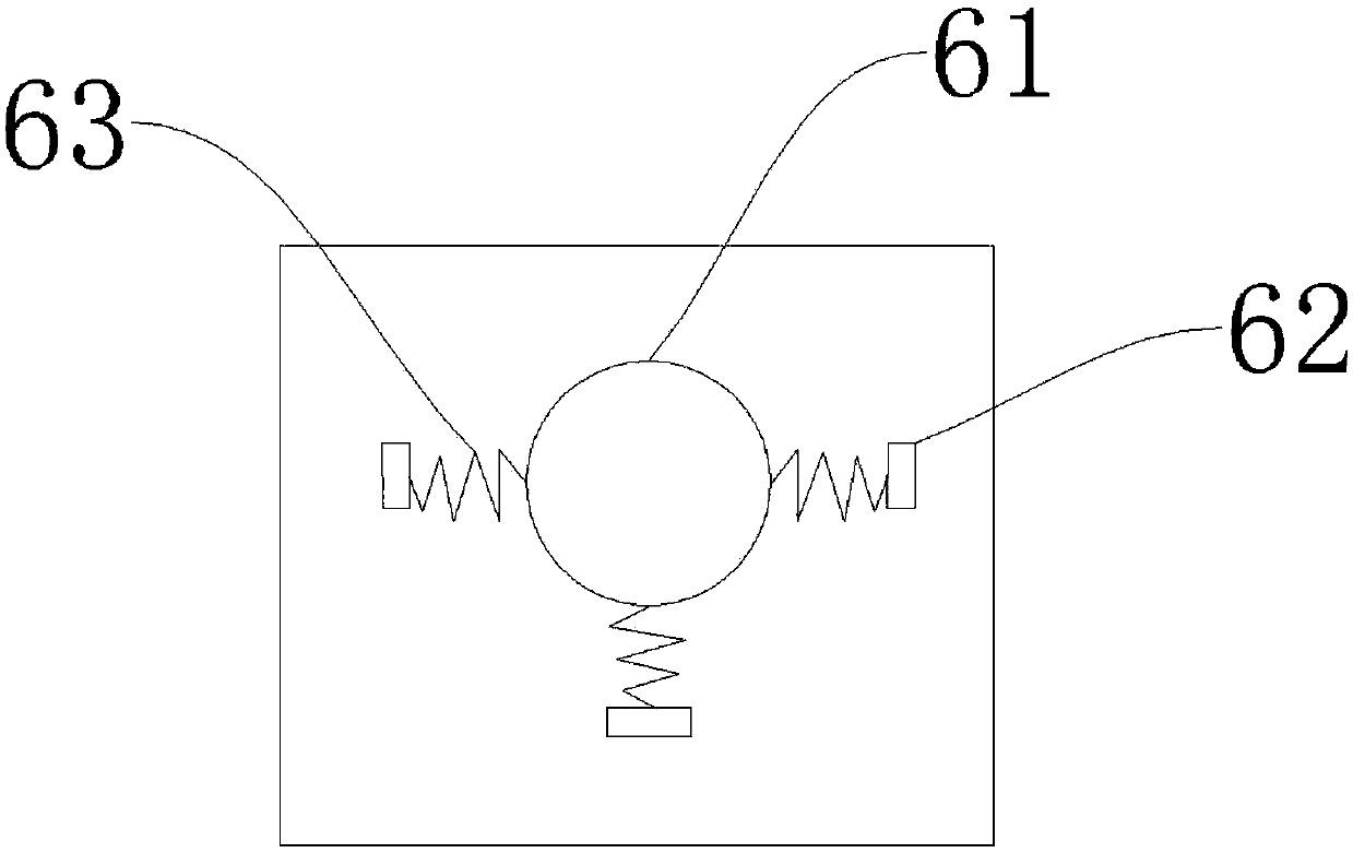
The invention discloses a floor projector stand which comprises a shell, a supporting column, an accommodating tank, a rotating shaft, a lifting locking assembly and a rotating locking assembly, wherein an electric jack is arranged inside the shell; the bottom of the supporting column is fixedly connected with a piston rod of the electric jack; a bearing sleeve is arranged at the top of the supporting column; a projector is placed inside the accommodating tank; the top of the rotating shaft is fixedly connected with the lower surface of the accommodating tank; the bottom of the rotating shaftis sleeved by the bearing sleeve; the lifting locking assembly comprises a pair of pneumatic telescopic rods, a lifting rod and a suction cup assembly; the lifting rod is connected with the movable ends of the pneumatic telescopic rods; the suction cup assembly is arranged on the lifting rod; the rotating locking assembly comprises a fixing sleeve, three L-shaped supporting rods and three springs;and when the end parts of the horizontal parts of the L-shaped supporting rods are all connected with the bearing sleeve, the springs are all in the natural state. By adoption of the floor projectorstand disclosed by the invention, the up-down adjustment and the 360-degree rotating adjustment of the projector can be achieved, thereby meeting the projection demand of the projector; and the floorprojector stand has no exacting demand for a floor placement point and can be properly placed according to the floor space, thereby improving the utilization ratio of the floor space.

Description

technical field [0001] The invention relates to the field of projection equipment, in particular to a stand for a floor projector. Background technique [0002] As a meeting and teaching tool, projectors are widely used at present. They are usually placed directly on the table or installed on the ceiling of conference rooms or classrooms through brackets. However, the usual projector brackets are directly installed , cannot be moved, it is only suitable for one type of projector to project in a fixed direction, and it cannot be used if you change another type of projector or want to change the projection direction. With the advancement of science and technology, mobile projection equipment has appeared, that is, a walking shelf is set up, and a projection screen and a projector are set on the shelf at the same time. Although this method does not need to install projection equipment in every classroom or meeting room, but This mobile projection device is bulky, inconvenient ...

Claims


Application Information

Patent Timeline
Patent Type & Authority Applications(China)
IPC IPC(8): F16M11/24F16M11/08F16M11/04
Inventor 陈梅慧陈松
Owner 黄世仁
Why Eureka
Try Eureka