Reverse flange structure of reactor pressure vessel with integrated steam channel

A reverse flange and pressure vessel technology, applied in reactors, sealing, reducing greenhouse gases, etc., can solve problems such as inability to adapt to high controllability, and achieve the effect of relatively thick wall, reasonable structure, and reduced manufacturing difficulty

Active Publication Date: 2019-08-27
NUCLEAR POWER INSTITUTE OF CHINA
View PDF9 Cites 0 Cited by
  • Summary
  • Abstract
  • Description
  • Claims
  • Application Information

AI Technical Summary

Problems solved by technology

[0004] In view of the above-mentioned existing reactor pressure vessel cylinder flange can only realize the sealing of the coolant in the primary circuit, it can no longer meet the development needs of modern reactors with reasonable structure, small wall thickness, controllable height, easy manufacture and convenient layout , the present invention provides a reverse flange structure of a reactor pressure vessel with integrated steam channels, the flange structure can reduce the diameter of the sealing ring, the thickness of the top cover, the height of the top cover, the height of the reactor and the weight of the reactor, and reduce the sealing ring and top cover. The difficulty of manufacturing the cover and the difficulty of axial arrangement of the reactor

Method used


Image

  • Reverse flange structure of reactor pressure vessel with integrated steam channel
  • Reverse flange structure of reactor pressure vessel with integrated steam channel
  • Reverse flange structure of reactor pressure vessel with integrated steam channel

Examples


Embodiment 1

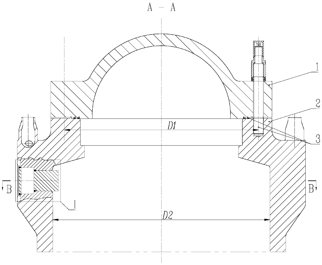
[0031] Such as Figure 1 to Figure 5 As shown, the reverse flange structure of the reactor pressure vessel with integrated steam channels is used for the connection between the barrel of the reactor pressure vessel and the top cover 1, and the reverse flange structure includes the reverse method Flange body 2, the reverse flange body 2 has a cylindrical structure with an inner diameter larger than the other end, and the end of the reverse flange body 2 with a smaller inner diameter is also provided with a plurality of bolt holes, the plurality of The bolt holes are evenly distributed on a ring, and the diameter of the ring is smaller than the inner diameter of the larger end of the opposite flange body 2 .

[0032] Specifically, this reverse flange is used as a connecting piece between the cylinder body of the reactor pressure vessel and the top cover 1, that is, when the reverse flange body 2 is in use, one end with a threaded hole is provided for connecting with the top cover ...

Embodiment 2

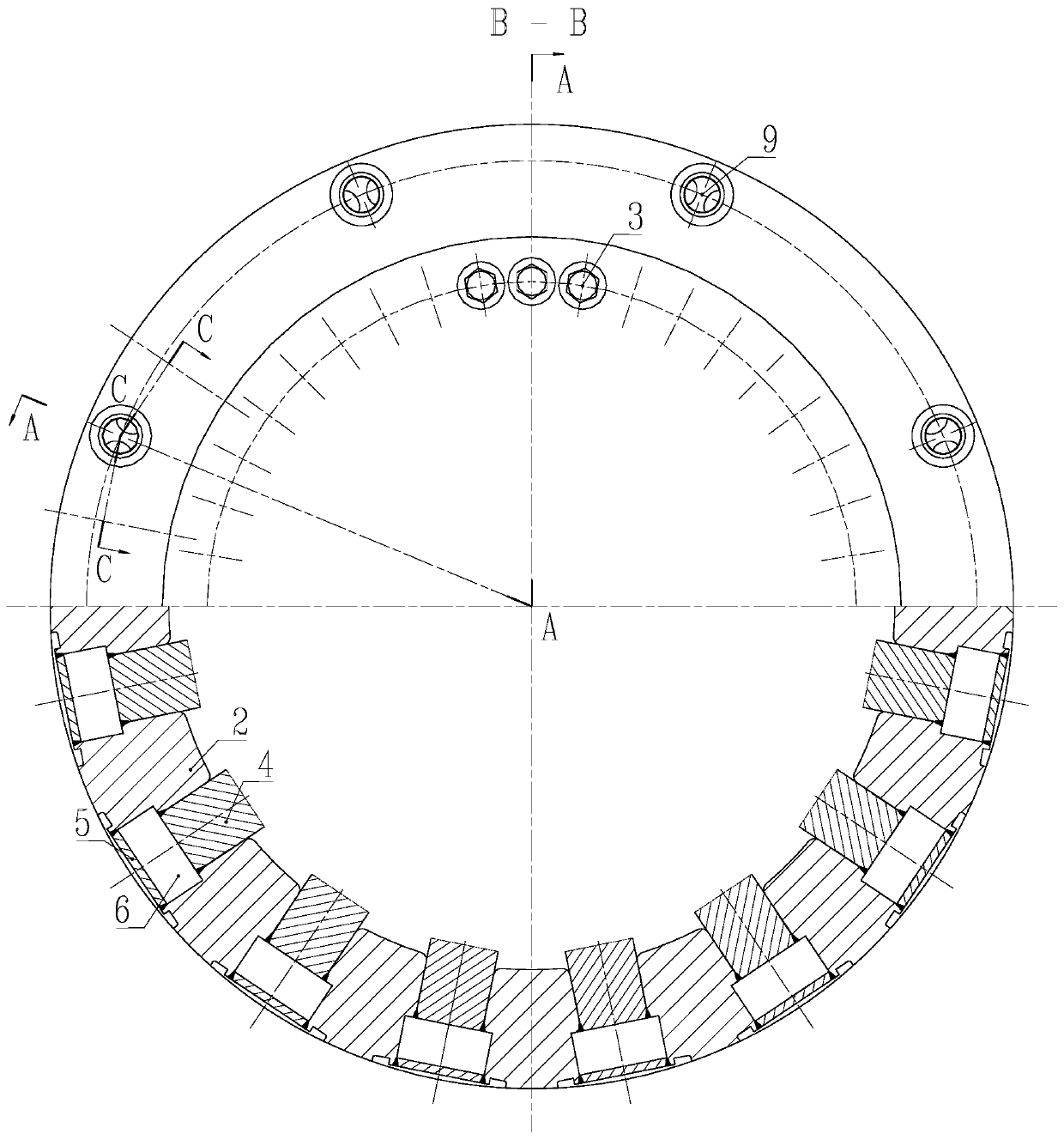
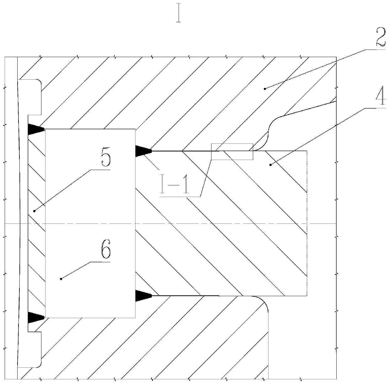
[0034] The present embodiment is further limited on the basis of embodiment 1, as Figure 1 to Figure 5 As shown, the reverse flange body 2 is also provided with a plurality of steam cavity holes 6, and each steam cavity hole 6 runs through the inside and outside of the side wall of the reverse flange body 2, and also includes the same number of steam cavity holes 6 There are equal number of end caps 5, and one end cap 5 is fixed on the end of each steam chamber hole 6 away from the center of the reverse flange body 2, and the end cap 5 is used as a sealing plate corresponding to the outer side of the steam chamber hole 6;

[0035] Each steam chamber hole 6 is provided with a steam generator 4 inside;

[0036] It also includes a steam hole 8 and a steam outlet connection 9 arranged on the reverse flange body 2 , and the steam hole 8 serves as an intermediate communication channel between the steam chamber hole 6 and the steam outlet connection 9 .

[0037] The above scheme pr...

Embodiment 3

[0047] This embodiment is further limited on the basis of any one of the technical solutions provided by any one of the above embodiments: in order to facilitate the connection between the reverse flange and the cylinder, the end of the reverse flange body 2 with a larger diameter is also set There are welding grooves.


PUM


Abstract

The invention discloses a reverse flange structure of a reactor pressure vessel with an integrated steam channel. The reverse flange structure is used for the connection between the cylinder body and the top cover of the reactor pressure vessel. To the flange body, the reverse flange body has a cylindrical structure with an inner diameter larger than the other end, and a plurality of bolt holes are arranged on the end with a smaller inner diameter of the reverse flange body, and the plurality of bolts The holes are evenly distributed on a circular ring, and the diameter of the circular ring is smaller than the inner diameter of the larger end of the inner diameter of the opposite flange body. The flange structure can reduce the diameter of the sealing ring, the thickness of the top cover, the height of the top cover, the height of the reactor and the weight of the reactor, and reduce the difficulty of manufacturing the sealing ring and the top cover and the difficulty of axial arrangement of the reactor.

Description

technical field [0001] The invention relates to the technical field of reactor structure design, in particular to a reverse flange structure of a reactor pressure vessel with integrated steam channels. Background technique [0002] As the pressure boundary of the reactor coolant system, the reactor pressure vessel is the main barrier for sealing radioactive substances and shielding nuclear radiation, so the reactor pressure vessel should have effective sealing; the reactor pressure vessel holds, fixes and supports the reactor internals and core The reactor internals and core components need to be hoisted in during commissioning and charging, and the reactor internals and core components need to be hoisted out during refueling maintenance. Therefore, the reactor pressure vessel should be detachable and can meet the requirements of reactor internals and core components. Access requirements for components. Therefore, the reactor pressure vessel usually consists of three parts:...

Claims


Application Information

Patent Timeline
Patent Type & Authority Patents(China)
IPC IPC(8): G21C13/02
CPCG21C13/02Y02E30/30
Inventor 李玉光王小彬方才顺罗英付强张亚斌尹祁伟周高斌董元元邱天
Owner NUCLEAR POWER INSTITUTE OF CHINA
Why Eureka
Try Eureka